Download
1 / 16
160 likes | 358 Views
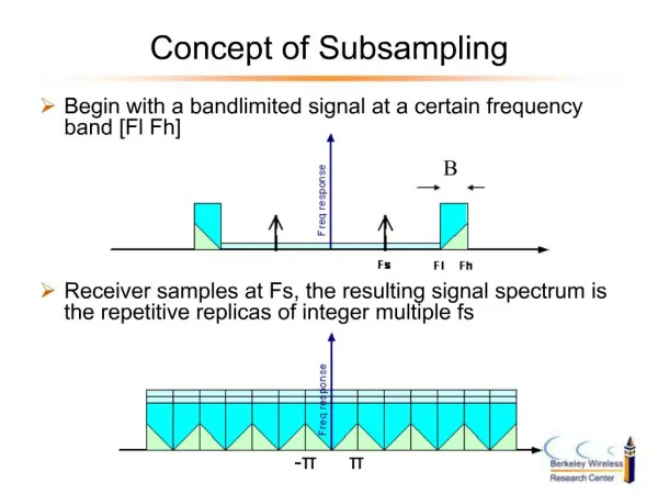
Concept of Subsampling. Begin with a bandlimited signal at a certain frequency band [Fl Fh]. . . Receiver samples at Fs, the resulting signal spectrum is the repetitive replicas of integer multiple fs. p. -p. . . B. Motivation. Motivation: - Among many existed wireless systems, UWB has to be somewhat different, such as cheaper and lower power. - Subsampling radio has fewer components compared to traditional heterodyne architecture. No analog multipliers and LO required for mixing. Chall30072

E N D
1. A Subsampling Radio Architecture for 3-10 GHz UWB Mike Shuo-Wei Chen
Prof. Bob Brodersen
June 13, 2003 BWRC Retreat
2. Concept of Subsampling Begin with a bandlimited signal at a certain frequency band [Fl Fh]
3. Motivation Motivation:
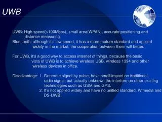
- Among many existed wireless systems, UWB has to be somewhat different, such as cheaper and lower power.
- Subsampling radio has fewer components compared to traditional heterodyne architecture. No analog multipliers and LO required for mixing.
Challenges of Subsampling:
- All thermal noise power between [-Fl�Fl] will fold back to signal band. The amount of aliasing is proportional to fc/B.
- RF bandpass filter design is harder than IF or baseband.
- Tighter sampling jitter requirement.
4. Why Promising for UWB? Much lower fc/B ratio than narrowband system
Let�s say 1 GHz pulse centered from 3~10 GHz
Noise level is dominated by the in-band noise & interference
Giga-hertz bandwidth will inevitably pick up the signals from other wireless systems
Q of RF bandpass filter is low
Lower number of ADC bits relaxes the jitter requirement
5. Integrated Analog Front End Radio Architecture:
- Wideband antenna
- Wideband amplifier / matching network
- RF bandpass filtering (low Q filter)
- High bandwidth sample and track
- High-speed and low resolution ADC
- Sampling Clock generator
- DSP
6. Different Transmitter Narrowband System:
A baseband signal is mixed up to carrier frequency UWB system:
Pulser drives antenna and generates a passband signal without mixer
7. How to recover the information? Reach the matched filter bound digitally without wideband analog processing. Another good example of taking the advantage of technology scaling.
How to know the matched filter response?
A: Simply use running average during training sequence. The best linear estimator, if the noise is AWGN.
A small shift of sampling time will change the sampled waveform dramatically. A timing recovery issue! Matched filtering failed�
A: Propose a Complex signal based digital backend
8. Sampling Process
9. Pulse Used in Simulation UWB pulse measured with monopole antenna. Pulse is then filtered by an ideal 3-4 GHz bandpass filter in Matlab.
10. Sampling Offset Effects Sampled pulse shape changes dramatically with fractional of sampling spacing!
11. Analytic Signal Processing Convert a discrete real signal into a discrete analytic signal via Hilbert transformer.
Real and imaginary part of the analytic signal are two orthogonal sets. The analogy is I and Q channel!
Analytic MF response: h(t) = s*(T-t).
12. Constellation @ Analytic MF outputs Timing offset cause the constellation to rotate.
13. Trajectory with infinite-bit ADC Sampling offset varies from 0.1Ts to 4Ts.
SNR of Real, Imag, Abs of analytic MF output.
Timing Information!
14. Trajectory with 1-bit ADC More averaging is needed or the robustness to the sampling offset is reduced.
15. Subsampling & Analytic Filtering Possible application:
Data communication or Ranging at a low cost
16. Conclusion A subsampling analog front end combined with analytic signal processing has been proposed for passband UWB communication.
By the magnitude of complex MF output, timing recovery has been done without interpolation or oversampling. Thus, it makes digital matched filtering promising and practical.
This technique also achieves a very fine timing resolution smaller than sampling rate, which implies high accuracy ranging capability. This is a special feature of UWB.
17. Future Work Sub-banding issue:
parallel filter banks or synthesizable LO banks
Bandpass RF filter implemetation:
a descent attentuation at stop band while low IL
Careful jitter budgeting:
pulse shape estimation and timing resolution
Interference cancellation:
analog , digital
System specs:
ADC bits, finite word length, etc.
Hopefully, more results can be shown in the next retreat.