Download
1 / 17
170 likes | 281 Views
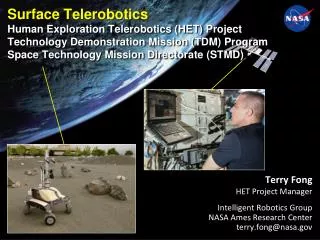
Surface Telerobotics Human Exploration Telerobotics (HET) Project Technology Demonstration Mission (TDM) Program Space Technology Mission Directorate (STMD). Terry Fong HET Project Manager Intelligent Robotics Group NASA Ames Research Center terry.fong@nasa.gov. Motivation.

E N D
Surface TeleroboticsHuman Exploration Telerobotics (HET) Project Technology Demonstration Mission (TDM) ProgramSpace Technology Mission Directorate (STMD) • Terry Fong • HET Project Manager Intelligent Robotics Group NASA Ames Research Center terry.fong@nasa.gov
Motivation Surface Telerobotics is an engineering test of a human-robot “opscon” for future deep-space human exploration missions • Candidate Missions • L2 Lunar Farside. Orion crew module test flight (~2020) to Earth-Moon L2 point • Near-Earth Asteroid. NEA dynamics and distance make it impossible to manually control robot from Earth • Mars Orbit. Crew must operate surface robot from orbit when circumstances (contingency, etc.) preclude Earth control • What will the test achieve? • Obtain baseline engineering data • Validate & correlate prior ground simulations • Reduce the risk that mission planning is based on inaccurate assumptions (NASA GSFC)
Surface Telerobotics • Objectives • Demo crew-centric control of surface telerobot from ISS (first operational system) based on L2 Lunar farside mission concept • Test human-robot “opscon” for future deep-space exploration mission • Obtain baseline engineering data of system operation • Approach • Leverage best practices and findings from prior ground simulations • Collect data from robot software, crew user interfaces, and ops protocols • Validate & correlate to prior ground sim(analog missions 2007-2011) • Implementation • K10 planetary rover in ARC Roverscape (outdoor test site) • ISS astronaut + Mission Control • L2 mission sims (3): June-Aug 2013(ISS Incr. 36: 10.5 hr total crew time) Crew on ISS K10 at NASA Ames • Key Points • Complete human-robot mission sim: site selection, ground survey, telescope deployment, inspection • Telescope proxy: COTS 75 micron polyimide film roll(no antenna traces, no electronics, no receiver) • 3.5 hr per crew session (“just in time” training, system checkout, telerobot ops, & crew debrief) • Two control modes: basic teleop and pre-planned command sequencing (with continuous monitoring) • Limited crew user interface: no sequence planning, no science ops capability, no robot engineering data
Objectives 1. Demonstrate that crew can remotely operate surface robots from inside a flight vehicle to perform exploration work • Ability to supervise planetary robot from space craft (make correct decisions, take appropriate action) • Awareness of intent and outcome of rover autonomous actions for waypoint driving, image acquisition, payload deployment • Ability to detect and respond appropriately to robot problems affecting achievement of mission objectives 2. Mature technology required for crew control of surface telerobots (specifically robotic control interfaces for crew) • Information and capability for supervisory control of robot • Information and capability for mission tasks of site selection, antenna deployment, and antenna inspection • Usefulness and understandability of robot’s autonomous functions for waypoint driving, image acquisition, and payload deployment • Availability and timeliness of information (communication & data distribution) 3. Identify requirements and gaps for research and technology development programs • Identify HRP risks and gaps relevant to Surface Telerobotics • Document evidence of HRP risks or HRP risks avoided observed during sessions
L2 Lunar Farside (Waypoint) Mission Concept • Orion at Earth-Moon L2 Lagrange point • 60,000 km beyond lunar farside • Allows station keeping with minimal fuel • Crew remotely operates robot on lunar farside • Less expensive than human surface mission • Does not require human-rated lander • Primary objective: lunar telescope • Use telerobot to setup radio telescope • Requires surface survey, antenna/receiver deployment, and inspection/documentation • Lunar farside provides radio quiet zone for low-freq measurements cosmic dawn • Secondary objective: sample collection • Use telerobot to perform field geology • Requires scouting, sampling (possiblysubsurface), and sample caching/return • South Pole Aitken (SPA) basin sampling is the highest priority lunar science objective (Lockheed Martin / LUNAR)
Polyimide Antenna Technology • Concept • Metallic conductor deposited on surface of polyimide film (e.g., DuPont Kapton) • Suitable for frequencies up to 100 MHz • Polyimide remains flexible at lunar daytime temperatures, thus can be deployed by unrolling • Testing (to date) • Vacuum chamber with thermal cycling & UV exposure similar to lunar surface conditions (Univ. of Colorado Boulder / NLSI LUNAR) • Outdoor signal test (New Mexico) (UC-Boulder / LUNAR) Rolling out polyimide film inside vacuum chamber with teleoperated mini-rover (UC-Boulder / LUNAR) Outdoor test in New Mexico
Telerobotic Telescope Deployment Concept (JPL / LUNAR)
Waypoint Mission Simulation (2013) Spring June 17 July 10 August 8
K10 Planetary Rover @ NASA Ames • K10 Specifications • 4-wheel drive, 4-wheel steer • Split rocker chassis • Size: 1.3 x 0.9 x 1.0 m (HxWxL) • Speed: 0.9 m/s (on 10 deg slope) • Power: 1900 W (Li-ion batteries) • Weight: 100 kg (with 25 kg payload) NASA Ames Roverscape
Deployed Telescope Simulation NASA Ames Roverscape
Robot Interface (Task Sequence Mode) Task Sequence Terrain hazards Rover camera display
Robot Interface (Teleop Mode) Rover path Motioncontrols Cameracontrols Terrain hazards Rover camera display
Data Communications Robot User Interface on SSC “Live” Rover Sensor and Instrument Data (telemetry) 384 kbits/sec (min), 5 sec delay (max) Uplink Rover/Science Data (e.g. imagery) Downlink Post-test File Transfer 384 kbits/sec (min), Out-of-Band Uplink, data transfer to laptop storage Note: Normal uplink ~1Mbps, spike after LOS is ~2Mbps for 2 sec Interface Instrumentation & Evaluation Data Rover Task Sequence (text file) 8 kbits/sec (min), 5 sec delay (max) K10 rover at NASA Ames
Tasks & Activities (ISS Crew) • Each crew session is 3.5 hours • Review, Training, Conference (1 hour) • Watch Intro Video, Read Big Picture Words (15 min) • Run through Just-in-time Training module (30 min) • Crew conference with PD team (15 min) • Surface Telerobotics Ops (2 hours) • Downlink task plans to robot and monitor execution • Interrupt execution for problems (e.g. cannot reach waypoint) • Handle contingencies as needed (run “teleop” plans) • Teleop to avoid obstacles • Perform additional data collection as needed to reacquire data • As observation data arrives, verify that data is valid • Interact with ground support as needed • Debrief with mission control (0.5 hours)
Technology Advancement TRL 4 = Component and/or breadboard validation in lab • TRL 5 = Component and/or brassboard validation in relevant environment (simulation of target operational environment) • TRL 6 = System/subsystem model or prototype demonstration in a relevant environment (under critical conditions). Engineering feasibility fully demonstrated. • TRL 7 = System prototype demonstration in an operational (space) environment. Well integrated with operational hardware/software.
Test Protocol • Data Collection Obtain engineering data through automatic and manual data collection • Data Communication: direction (up/down), message type, total volume, etc. • Robot Telemetry: position, orientation, power, health, instrument state, etc. • User Interfaces: mode changes, data input, access to reference data, etc. • Robot Operations: start, end, duration of planning, monitoring, and analysis • Crew Questionnaires: workload, situation awareness, criticial incidents • Metrics Use performance metrics* to analyze data and assess human-robot ops • Human: Bedford workload rating scale & SAGAT (situation awareness) • Robot: MTBI, MTCI for productivity and reliability • System: Productive Time, Team Workload, and task specific measures for effectiveness and efficiency of the Human-Robot system automatic manual * Performance metrics used for prior analog field tests: 2009 robotic recon, 2010 lunar suface systems, 2010 robotic follow-up, 2009-2011 Pavillion Lakes research project, etc.
Schedule 11/29/11 ISS Payloads Office authorization received 1/30/12 ISS Research Planning Working Group approval received 9/5/12 PCM (PLUTOs, Flight Director, MSFC, Ames) 11/13/12 SSC Lab testing 11/26/12 JSL Lab Testing for first Comm Test 11/29/12 SSTF-based end-to-end test 1/28/13 First ISS-to-ground Comm Test 3/13 – 5/13 Engineering and Ops Readiness Tests at Ames 4/3/13 Crew Usability Test – SSTF to Rover at Ames 5/8/13 JSL Lab Testing for Crew Ops 6/10/13 Second ISS-to-ground Comm Test (due to ODAR, etc.) 6/17/13 Crew Ops session #1 – Site survey 7/22/13 (tbc) Crew Ops session #2 – Antenna deploy 8/5/13 (tbc) Crew Ops session #3 - Inspection