Download
1 / 31
310 likes | 434 Views
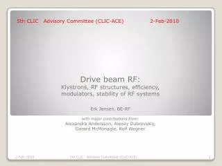
Drive beam RF: Klystrons, RF structures, efficiency, modulators, stability of RF systems Erk Jensen, BE-RF with major contributions from: Alexandra Andersson , Alexey Dubrovskiy , Gerard McMonagle , Rolf Wegner. 5th CLIC Advisory Committee (CLIC-ACE) 2-Feb-2010. Outline.

E N D
Drive beam RF: Klystrons, RF structures, efficiency, modulators, stability of RF systemsErk Jensen, BE-RFwith major contributions from: Alexandra Andersson, AlexeyDubrovskiy, Gerard McMonagle, Rolf Wegner 5th CLIC Advisory Committee (CLIC-ACE) 2-Feb-2010 5th CLIC Advisory Committee (CLIC-ACE)
Outline Power sources: Klystrons Modulators Efficiency (2nd look at IOT’s) Accelerating structures Stability/Stabilisation Measurements at CTF3 Feed-forward Phase monitor Globally distributed reference 5th CLIC Advisory Committee (CLIC-ACE)
CLIC Drive Beam RF System – issues: • Reminder of the main issues for the Drive Beam RF system: • Very large total power (≈23 GW peak, 170 MW average) What power source? Optimum size of individual power source? This was addressed in the last ACE. • Phase stability (jitter <50 fs) • Overall efficiency! • Cost! • Summary from last ACE: Trends: • MBK 10 MW ... 20 MW • 10 MW available today (X-FEL, ILC) • “smaller” klystrons make reliability and serviceability easier ... remained to be done: • Make group delay of acc. structure = length of delay loop • Redesign structures to optimize for beam dynamics requirements 5th CLIC Advisory Committee (CLIC-ACE)
Klystrons ... not much new, but converging for CDR: 5th CLIC Advisory Committee (CLIC-ACE)
Reminder: from last year’s ACE 5th CLIC Advisory Committee (CLIC-ACE)
What’s new about the klystrons? Questionnaire prepared and sent to klystron manufacturers (CPI, Thales, L3, E2V, Toshiba, Istok, Chinese industry) asking about the feasibility of a 20 MW klystron (4 different scenarios) So far, only CPI replied: • Reasonable to start from ILC/X-FEL klystrons • 20 MW, 150 μs, 50 Hz, 65 % ... feasible (≈ 8 beams), • design & proto estimate: 2 M$ and 2 years, • series cost estimate 1.1 M$ (55 k$/MW), • delivery schedule: month 12, 14, 16, ... ARO • They tend towards slightly higher voltage (150 kV?) This sounds reasonable for the conceptual design. 5th CLIC Advisory Committee (CLIC-ACE)
Modulators ... not much new 5th CLIC Advisory Committee (CLIC-ACE)
Reminder: from last year’s ACE 5th CLIC Advisory Committee (CLIC-ACE)
ScandiNova’s K2-SYSTEM for PSI; 351kV / 416A ! Achieved pulse to pulse stability: ± 4 10-5 5th CLIC Advisory Committee (CLIC-ACE)
Efficiency ... not for CDR, but for later other possibilities should be considered: 5th CLIC Advisory Committee (CLIC-ACE)
IOT’s – a second look: According to CPI, IOT’s would be a natural choice for highest efficiencies; CPI’s claims: • IOT VHP-8330 reached 930 kW @ 700 MHz. • up to 1.5 MW at 1 GHz should be possible, • > 80 % efficiency at this power level are possible, • IOT’s would be cheaper/MW (!) • typical DC voltage range: 35 kV, • no modulator necessary → pulses via RF drive! ηKlystron ηModulator ≈ 60 % would become ηIOT ηpower distribution ≈ 70 %; this would reduce wall plug power quite significantly! • no saturation → power regulation with feedback possible. • gain ≈ 22 dB (needs 10 kW drive for 1.5 MW) Disadvantages: less gain, no operational experience, more complex power distribution! 5th CLIC Advisory Committee (CLIC-ACE)
Multi-beam HOM IOT’s left: existing VHP-8330 right: planned VKP-8330B 5th CLIC Advisory Committee (CLIC-ACE)
Conclusion power sources • For the CDR, MBK’s derived from ILC/X-FEL with 15 to 20 MW are realistic. • Some of the features of IOT’s make them appear interesting – a more detailed analysis is necessary. • At the same time we’re trying to analyze (fellow to start in September 2010) higher η klystrons. 5th CLIC Advisory Committee (CLIC-ACE)
Accelerating Structures 5th CLIC Advisory Committee (CLIC-ACE)
Input power for full beam loading for different cell numbers New interesting region former “nominal” ≈ 28.3 kW · ncell2 5th CLIC Advisory Committee (CLIC-ACE)
Pb Pb RBP Pin Pout Redesign of accelerating structure Rolf Wegner’s work: SICA -- constant aperture gapn Ncells E0T Vacc η= ΔPb/Pin tfill mode spectrum 5th CLIC Advisory Committee (CLIC-ACE)
New optimum accelerating structure 5th CLIC Advisory Committee (CLIC-ACE)
Reminder: Why 245 ns group delay? 5th CLIC Advisory Committee (CLIC-ACE)
New structure design (R. Wegner) Scaled from 3 GHz: New design: Outer Ø: 522 mm Outer Ø: < 300 mm New idea (A. Grudiev): dampers inside the slots! This new approach has been verified: acc. mode Q0= 2.2 ∙104, Qext= 3.7∙107 5th CLIC Advisory Committee (CLIC-ACE)
Verification of efficient damping 5th CLIC Advisory Committee (CLIC-ACE)
Conclusion accelerating structures: • SICA structures were successfully redesigned and re-optimized for 1 GHz (thanks to Rolf Wegner!). • Design includes: • Optimum aperture – to be finalized with BD simulations • Optimum RF efficiency • Optimum group delay (≈ 245 ns) • New idea for dipole mode damping verified • Moderate outer Ø < 300 mm • The coupler design is ongoing. 5th CLIC Advisory Committee (CLIC-ACE)
Phase stabilisation 5th CLIC Advisory Committee (CLIC-ACE)
Phase stability measurement at CTF3 AlexeyDubrovskiy analyzed phase- and amplitude stability of 4 CTF3 klystrons. Example given here: MKS03 • Result: • W/o special measures, the pulse-to-pulse phase jitter is 0.1 ... 0.15°. • This is “only” a factor 5 ... 8 away from our specification of 0.02°! • Reminder: with feed-forward (see below), we’re probably about OK! • This is very encouraging! phase in deg. sample # time 5th CLIC Advisory Committee (CLIC-ACE)
Phase measurement and correction scheme A. Andersson: CLIC Workshop 14-Oct-09 5th CLIC Advisory Committee (CLIC-ACE)
The phase monitor • Requirement: low impedance, 20 fs resolution • Status: Task 9.5 in the Work-package NCLinac of the EuCARD FP7 project (in collaboration with PSI and INFN/LNF), making good progress. • Double-mirror concept developed (F. Marcellini) s21, s31 5th CLIC Advisory Committee (CLIC-ACE)
Global vs. local timing reference Highly stable globally distributed REF de-magnifies MB jitter dependence For a more detailed analysis, including influence of feed-forward, see D. Schulte’s presentation 5th CLIC Advisory Committee (CLIC-ACE)
Local Oscillator • We need an LO with « 23 fs integrated phase jitter. • The beam path provides some noise filtering below 3 kHz • The system here seems to come in around ~ 4 fs noise power density dBc/Hz O(5k€) 5th CLIC Advisory Committee (CLIC-ACE)
Global Optical Phase-stable Timing Distribution? • Major developments underway in the field, primarily for X-FEL type light-sources. • Two relevant presentations at the last CLIC workshop: • F. Ömerİlday, BilkentÜniversitesi: Long-distance optical stabilization with femtosecond resolution, (http://indico.cern.ch/contributionDisplay.py?contribId=96&sessionId=6&confId=45580) • Matthias Felber, DESY: Femtosecond Optical Synchronization System for FLASH (http://indico.cern.ch/contributionDisplay.py?contribId=100&sessionId=6&confId=45580) • Still requiresmajorworkand break throughs in order toworkover CLIC distances 5th CLIC Advisory Committee (CLIC-ACE)
Timing-stabilized fiber links PZT-based fiber stretcher fiber link < 5 km 50:50 coupler Master Oscillator isolator OC coarse RF-lock <20 fs optical cross- correlator ultimately < 1 fs 5th CLIC Advisory Committee (CLIC-ACE)
From Ömerİlday’s talk: Concepts for φ-REF distribution optic-atomic clock divide and conquer Multiple stations with individual master oscillators and mutual links form a chain Laser frequency combs locked to a precise quantum transition, can be absolutely stable. Position one at each major point, distribute sync signal locally as before. Use long links to keep each clock locked to each other (slow corrections). Distribution of frequencies with 10-14 precision has been demonstrated. 5th CLIC Advisory Committee (CLIC-ACE)
Conclusions phase stabilisation: • Phase stability measurements at CTF3 gave encouraging values. • A feed-forward, measuring the phase jitter in the drive beam and correcting for it, can significantly relax the requirements (factor 10). • The low-impedance, high resolution phase monitor is addressed in FP7/EuCARD and makes correct progress. • A stable, globally distributed reference can demagnify the dependence on the main beam jitter further by a factor 7. • For global distribution of ultra-stable phase references, strong synergy with the X-FEL community exists. 5th CLIC Advisory Committee (CLIC-ACE)