Download
1 / 15
150 likes | 284 Views
PS-to-SPS longitudinal beam transfer studies. Helga Timkó BE-RF-BR in collaboration with Heiko Damerau , Theodoros Argyropoulos , Thomas Bohl , Steven Hancock, Juan Esteban Müller, Elena Shaposhnikova. Introduction & motivation.

E N D
PS-to-SPS longitudinal beam transfer studies Helga Timkó BE-RF-BR in collaboration with HeikoDamerau, TheodorosArgyropoulos, Thomas Bohl, Steven Hancock, Juan Esteban Müller, Elena Shaposhnikova
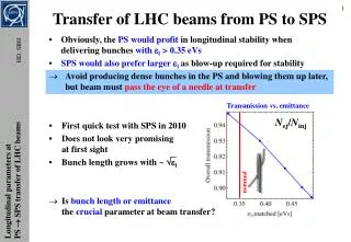
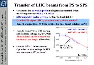
Introduction & motivation • Continuous efforts to optimise the PS-SPS transfer for several years • In the past:the aim was to reduce losses • For low SPS capture voltages, losses were unacceptable 20-40 % (2004) • Now:only ~5 % losses for the nominal intensity (due to long optimisation and less e-cloud) • However, relative losses increase with intensity will be an issue • Using a larger εlis desirable for stability in the PS & SPS • Will also be more critical for future higher intensities • In measurements till 2011no loss reduction could be achieved • Idea: shorter τ using higher voltage for the PS bunch rotation • Result: even though got significantly shorter, loss remained the same • This scheme didn’t work and it wasn’t understood why… LIU Beam Studies Review
Simulations • The LHC-type 50 ns and 25 ns beam has been modelled with ESME • Single bunch simulations, without intensity effects • Using averaged, real bunch distributions, measured at PS FT (with the tomoscope) • Full tracking of PS & SPS RF manipulations • PS: adiabatic voltage reduction, double splitting(s), bunch rotation; • SPS: FB, in some cases also ramp • Capture losses dominated by losses from the bunch tails • Shorter bunches do not necessarily result in the best transmission • Need to optimise the particle distribution in phase space – not visible from bunch profiles, sims. needed! Operational bunch-to-bucket transfer LIU Beam Studies Review
Measurements • First measurements started in 2011, 8 MD sessions in 2012 • Dedicated cycle for parallel-MD measurements • Single batch, 50 ns spaced LHC-type beam • Intensity:~1.6 1011 ppb, except for one MD (intensity studies) • Varying the PS rotation timings t40 MHz and t80 MHz to optimise the distrib. • Using the spare 40 MHz and 80 MHz cavities in the PS to increase the rotation voltage • Bunch length: • at PS ejection • Transmission: • (intensity at 30 GeV) / (injected intensity) • In the simulations: • only capture + FB losses LIU Beam Studies Review
Option 1:Use the spare 80 MHz cavity • Simulations predict: optimum at t40MHz = 200-220 μs, t80MHz= 100 μs • Gain compared to operational settings: • T = 95.6 % 97.9 %; L = 4.4 % 2.1 % LIU Beam Studies Review
Option 1: Measurement results • Optimal settings for V40MHz = 300 kV, V80MHz = 900 kV: t40MHz = 240 μs, t80MHz = 100 μs • Gain compared to operational settings T = 95.4 % 96.3 % L = 4.6 % 3.7 % • N.B. constant offset of transverse losses LIU Beam Studies Review
Option 2:Use the spare 40 MHz cavity • Simulations predict: optimum at t40MHz = 130 μs, t80MHz= 80 μs • Gain compared to operational settings: • T = 95.6 % 98.1 %; L = 4.4 % 1.9 % LIU Beam Studies Review
Option 2: Measurement results • Optimal settings for V40MHz = 600 kV, V80MHz = 600 kV: t40MHz = 130 μs, t80MHz = 90 μs • Gain compared to operational settings T = 94.8 % 97.7 % L = 5.2 % 2.3 % LIU Beam Studies Review
Spare 80 MHz cavity:Emittance dependence • Now we understand the results of previous years… Operational The new scheme reduces losses Earlier MDs with spare 80 MHz cavity optimised only τ LIU Beam Studies Review
Spare 40 MHz cavity:Emittance dependence • Gives a better transmission and shorter bunches! Operational Operational transmission even with ~40 % larger εl! Optimised transmission with the spare 80 MHz cavity LIU Beam Studies Review
Spare 40 MHz cavity:Intensity dependence • About ~ 15 % higher intensity with the same transmission W/ spare 40 MHz cavity Operational LIU Beam Studies Review
Balance • Using the spare 40 MHz cavity has some clear advantages over the 80 MHz cavity: • Better transmission • Shorter bunch length • Emittance margin: 40 % (!) • Intensity margin: 15 % • Spare 40 MHz cavity not needed for ions (unlike the spare 80 MHz) • The new scheme still needs to be tested in an operational cycle, but the spare 40 MHz cavity is currently unavailable • Even if beam losses currently don’t cause concerns, stability is a key issueat the present intensity, both in the PS & SPS • SPS Q20; PS maybe the spare 40 MHz cavity could be a solution? • Empirical longitudinal stability scaling in the PS (at low intensities): Nb/εl = const. in theory, could gain up to 40 % in intensity LIU Beam Studies Review
PS hardware requirements • Using a spare 40 MHz cavity is ‘for free’(only minimal low-level hardware required) • Requires improved operational availability of the 40 MHz cavities (e.g. new power supplies) • Do we need the luxury of having a spare cavity? • If a cavity fails, we still can go back to the currently operational settings • Adding a 3rd40 MHz cavity to the PS is an option, too • But: at significant cost and manpower effort LIU Beam Studies Review
Conclusions • Simulations determined the loss mechanism of the PS-SPS transfer and agree very well with previous and present measurement results • The optimum phase space particle distribution at PS extraction has been obtained by simulations, and confirmed by experiments • Can significantly improve the transmission • Or provide a ~40 % emittance margin while keeping the same transmission • Has the potential to improve beam stability in the PS and, hence, allows for higher-intensity beams • Low-cost solution • Once the spare 40 MHz cavity is available again, the new scheme still needs to be tested under operational conditions LIU Beam Studies Review
Discussion • At high intensities: unstable beam in the PS and the SPS is sensitive (with Q26) to the injected beam quality, see talk of T. Argyropoulos • LHC acceptance can also be improved using larger emittance in the PS • How about Q20? • Beam is more stable in Q20 in the SPS, so no or little emittance blow-up in the SPS will be necessary beam quality from the PS will be preserved • Hence, it is even more important to have good beam qualityalready at injection to the SPS (i.e. larger emittance) • The improved PS rotation settings allow for larger emittance • At higher intensities, a larger emittance is necessary also for PS stability • In Q20, injection into relatively low voltages was successful the FB voltage can still be increased to capture larger emittances LIU Beam Studies Review