Download
1 / 38
380 likes | 557 Views
10BASE-T Hub. Collision Domain. Rivier College CS575: Advanced LANs Ethernet. Overview. A Brief History of Ethernet IEEE 802.3 10BASE5 Standard IEEE 802.3 10BASE2 Standard IEEE 802.3 10BASE-T Standard Media Access Control Ethernet Frame Format Collision Domain Concept Bridge Concept

E N D
10BASE-T Hub Collision Domain Rivier CollegeCS575: Advanced LANsEthernet Ethernet
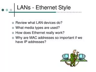
Overview • A Brief History of Ethernet • IEEE 802.3 10BASE5 Standard • IEEE 802.3 10BASE2 Standard • IEEE 802.3 10BASE-T Standard • Media Access Control • Ethernet Frame Format • Collision Domain Concept • Bridge Concept • Ethernet Switches Ethernet
A Brief History of Ethernet • Ethernet was invented by Bob Metcalfe and David Boggs in 1973 at the Xerox Palo Alto Research Center (PARC) as a local area network (LAN) for resource sharing among the researchers at the Center • The original PARC Ethernet was developed to run at 3 Mbps data rate • In 1979, Digital, Intel, and Xerox (DIX) formed a consortium to develop Ethernet specification • In 1980, the DIX Ethernet specification (Ethernet blue Book), Ethernet Version 1.0, was published • The data rate for the DIX Ethernet was specified as 10 Mbps • Over the next two years, DIX refined the Ethernet and issued the Ethernet Version 2.0 specification in 1982 • In the same year, the Ethernet Version 2.0 specification was submitted it to IEEE for standardization Ethernet
A Brief History of Ethernet (concluded) • On December 19, 1982, IEEE made some minor changes to the Ethernet specification Version 2.0 and released the first version of the IEEE 802.3 standard • The IEEE 802.3 standard has been adopted by numerous national and international standards bodies, including the National Institute of Standards and Technology (NIST), the European Computer manufacturers Association (ECMA), and the American National Standards Institute (ANSI) • In 1990, the IEEE 802.3 standard became part of the International Standardization Organization (ISO) standards, known as ISO/IEC 8802-3 standard • More than 85% of all installed network connections were Ethernet Ethernet
IEEE 802.3 10BASE5 Standard • In 1983, the IEEE 802.3 standard was finalized as the 10BASE5 standard • 802.3 is technically different from DIX Ethernet 2.0, but the differences are minor • Today, Ethernet and 802.3 are considered as synonymous • The DIX Ethernet 2.0 specification and the original IEEE 802.3 standard specified the use of a 50-ohm, 0.4-inch (10-mm) diameter, baseband coaxial cable as the transmission medium • This is sometimes referred to as the Thick Ethernet • A bus topology was specified to support 10 Mbps Manchester digital signaling • With these parameters, the maximum length of the cable is set at 500 meters • Stations attach to the cable by means of taps (transceivers) Ethernet
IEEE 802.3 10BASE5 Standard (concluded) • A maximum of 100 taps is allowed on each 500-meter cable segment • This Ethernet configuration is referred as the 10BASE5 Ethernet • To extend the length of the network, repeaters may be used to joint cable segments • The standard allows a maximum of 4 repeaters in the path between any two stations extending the effective length of the medium to 2500 meters (5 cable segments maximum) • This is known as the 4 repeaters and 5 cable segments rule • Since all stations are sharing the same cable, there will be a collision when two or more stations transmit at the same time • A medium access control protocol must be used to arbitrate the access of the network Ethernet
A Multiple Segment 10BASE5 Ethernet Example Repeater Repeater Ethernet
10BASE5 Medium Attachment Unit • 10BASE5 specifies the use of an external Medium Attachment Unit (MAU) to attach a station to a cable segment • The MAU is most often implemented in a device called a transceiver • A transceiver is clamped directly onto the coaxial cable Ethernet
10BASE5 Medium Attachment Unit (concluded) • An Attachment Unit Interface (AUI) cable is used to connect a station to its MAU • The AUI defines the cable and the connectors to be used • The maximum length for the AUI cable (also called the transceiver cable) is limited to 50 meters • Transceiver (MAU) functions • Transmit • Receive • Collision detection • Jabber Interrupt Ethernet
IEEE 802.3 10BASE2 Standard • To provide a lower cost system for personal computer LANs, IEEE 802.3 added a 10BASE2 standard in 1984 • The main difference is to implement a less expensive, thinner, 0.25-inch (5-mm) diameter 50-ohm coaxial cable • As with 10BASE5, 10BASE2 specified the same bus topology and Manchester digital signaling at a data rate of 10 Mbps • Since the thinner cable is more flexible, it is easier to bend around corners and bring to the workstation • The thinner cable also suffers greater attenuation and lower noise resistance than the thick cable • The maximum cable segment length is limited to 185 meters and up to 30 stations are supported per cable segment • To extend the length of the network, repeaters may be used to joint cable segments Ethernet
IEEE 802.3 10BASE2 Standard (concluded) • This Ethernet configuration is referred as the 10BASE2 Ethernet or sometimes dubbed as the CheaperNet • Cost savings for 10BASE2 • Cheaper, thinner cable • No need for external transceiver (MAU) and drop cable • The MAU is integrated with the station (NIC) • A BNC “T” connector is used to connect a station to the cable • A workstation with 10BASE5 NIC can attach to 10BASE2 cable with an AUI to 10BASE2 adapter Ethernet
10BASE2 Ethernet Example Ethernet
10BASE2 Ethernet with A Repeater Source: LANTRONIX Ethernet Product Guide Ethernet
IEEE 802.3 10BASE-T Standard • By sacrificing some distance, it is possible to develop a 10 Mbps LAN using the unshielded twisted-pair (UTP) medium • In 1990, IEEE 802.3 added the 10BASE-T standard to the 802.3 family • The 10BASE-T specification defines a star-shaped topology • A simple system consists of a number of stations connected to a central point, referred as a hub, or multiport repeater, via two unshielded twisted pair cable • The type of connector most often used with 10BASE-T cabling is the RJ-45 modular connector Ethernet
IEEE 802.3 10BASE-T Standard (concluded) • Adapters are also available for stations having AUI interfaces or 10BASE2 connectors to be connected to a 10BASE-T hub • The data rate is 10 Mbps using Manchester encoding • Because of the high data rate and the poor transmission quality of unshielded twisted pair, the length of the link is limited to 100 meters • UTP cable offers many advantages over thick and thin coaxial cable • UPT is less expensive, easier to handle, and similar to the telephone cable that may already be installed in the building • UTP cables come in a variety of grades • Category 3 and category 5 UTP cables have received most attention for LAN applications • Cat. 3 UTP is less expensive and more popular for 10BASE-T configurations, but Cat. 5 UTP is becoming increasingly common for pre-installation in new office buildings Ethernet
10BASE-T Ethernet Example Ethernet
10BASE-T Ethernet Expended Configuration Source: LANTRONIX Ethernet Product Guide Ethernet
Logical Link Control Medium Access Control Physical Medium Medium OSI Reference Model and IEEE 802 Protocol Layers IEEE OSI Ethernet
Media Access Control • Since all devices on an Ethernet share the same medium, to avoid collision, only one station is allowed to transmit at any time • Ethernet and 802.3 specified a Carrier Sense Multiple Access with Collision Detection (CSMA/CD) protocol to control the access of the medium • The basic rules for the CSMA/CD protocol • A station must listen to the medium first before transmit • If the medium is idle, the station is allowed to transmit • If the medium is busy, the station must continue to listen until the channel is idle, then transmit immediately • While transmitting, the station must continue to listen to the channel • If a collision is detected during transmission, the station must transmit a brief jamming signal to assure that all stations know that there has been a collision and then cease transmission Ethernet
Media Access Control (continued) • After transmitting the jamming signal, the station must wait a random amount of time and then attempt to transmit again • With random delay, the two stations involved in a collision are unlikely to collide on their next try • To ensure network stability, IEEE 802 and Ethernet specified a technique known as binary exponential backoff • A station will attempt to transmit repeatedly in the face of repeated collisions, but after each collision, the mean value of the random delay is doubled • After 16 unsuccessful attempts, the station gives up and reports an error • The key advantage of the CSMA/CD protocol with binary exponential backoff is thataccess to the medium is typically very fast as long as traffic is not heavy, since a station can transmit at any time the medium is idle Ethernet
Media Access Control (continued) • Since signal is Manchester encoded, any transmission on the medium will be detected Source: Stallings: Data and Computer Communications Ethernet
Media Access Control (concluded) • Performance issues • Under heavier traffic loads, the number of collisions increases and the time spent responding to collisions and retransmission may cause performance to degrade • Reasons for 4-repeater/5-segment rule • Reasons why the number of stations per segment is limited • Collision detection for 10BASE-T via the repeater (hub) • A hub receives a signal on any input link is repeated on all output links • If two inputs occur, causing a collision, a collision enforcement signal is transmitted on all links • If a collision enforcement signal is detected on any input, it is repeated on all other links Ethernet
0 -46 bytes 7 bytes 1 byte 6 bytes 6 bytes 2 bytes 4 bytes 0 -1500 bytes Source Address Destination Address Data Length Pad FCS Preamble SFD Ethernet Frame Format IEEE 802.3 Frame Format 46 -1500 bytes 6 bytes 6 bytes 2 bytes 4 bytes 8 bytes Source Address Destination Address Type Data FCS Preamble DIX Ethernet Frame Format Ethernet
Ethernet Frame Format (concluded) • Preamble • Start Frame Delimiter • MAC Addresses • Type/Length • Maximum Frame Size: 1518 bytes (14 bytes header + 1500 bytes data + 4 bytes FCS) • Minimum Frame Size : 64 bytes (14 bytes header + 46 bytes data + 4 bytes FCS) • Interframe Gap: 9.6 microseconds Ethernet
Summary Table Ethernet
10BASE-T Hub Collision Domain Collision Domain Concept Ethernet
Collision Domain Concept (concluded) 10BASE-T Hub 10BASE-T Hub Collision Domain Ethernet
Bridge Concept Bridge Fast Ethernet Repeater Fast Ethernet Repeater Collision Domain Collision Domain Ethernet
Bridge Concept (continued) • A bridge is a network interconnection device used to join together two or more separate LANs to create a larger or an extended LAN • Sometimes it may be necessary to use a bridge to split what is logically a single LAN into separate LANs to accommodate the traffic load • A bridge performs its functions in the OSI model Data Link layer • The device is designed for use between LANs that use identical protocols for the physical and medium access layer (e.g., all conforming to IEEE 802.3 or all conforming to IEEE 802.5) • Because the devices all use the same protocols, the amount of processing required at the bridge is minimal • Low cost and ease of use are the advantages of the bridge • Some more intelligent bridges are designed to for use between LANs with dissimilar protocols • Two types of bridges Ethernet
Bridge Concept (continued) • Transparent bridge • Source routing bridge • In a building with multiple LANs, bridges may need to determine how to forward frames in a very complex network configuration to reach the destination • It is difficult and time consuming to manually configure all the bridges • A transparent bridge is a self learning, plug-and-play bridge • Once power up, it observes transmissions that take place on each connected LAN segment and learns which stations can be reached over which LAN segment • A transparent bridge is sometimes called a spanning tree bridge • The operation of transparent bridge is specified in the IEEE 802.1d standard Ethernet
Bridge Concept (continued) Multiple LANs Interconnected by Bridges Source: Stallings: Local & metropolitan area Networks Ethernet
Bridge Concept (continued) Source: Stallings: Local & metropolitan area Networks Ethernet
Bridge Concept (concluded) • Source routing bridges use routing information included in the message header to determine the path the frame should take through the complex network configuration Ethernet
Ethernet Switches • 10BASE-T Ethernet can be implemented in either hubs (repeaters) or switches • In 1990, Kalpana developed the first Ethernet switch, EtherSwitch EPS-700 • The technology of Ethernet switch is similar to the intelligent multiport bridge • The hub is a shared medium technology (medium access control such as CSMA/CD is needed) and the switch is a dedicated medium technology (no medium access controls are needed) • Support multiple, independent conversations, i.e., messages are simultaneously switched between any idle ports (like a telephone switch or ATM switch) • Network capacity scales with number of ports • Improve network privacy due to dedicated bandwidth • Provide wire-speed performance Ethernet
Ethernet Switches (continued) • Support full-duplex operation, which increases the effective throughput to 20 Mbps per port • Use existing 10BaseT wiring infrastructure • CSMA/CD protocol is no longer needed; no collisions can happen • Multiple switches can be used to extend Ethernet network diameter as well as supporting more nodes • Most switches are “plug-and-play” self learning devices for packet forwarding Ethernet
Ethernet Switch Switching Schemes • Three switching schemes • Store-and-forward • Cut-through • Fragment Free (Modified cut-through) 7 bytes 1 byte 6 bytes 6 bytes 2 bytes 1500 bytes Max 4 bytes Source Address Destination Address Length FCS Preamble SFD Data After 64 bytes Cut-through Fragment Free Store-and-forward Lowest latency Low latency, collision detection High latency, error detection Ethernet
Cost & References Source: Data Comm Warehouse (1999) COST: • Asante 8-port 10BASE-T Hub: $59.95 • Asante 24-port 10BASE-T Hub: $269.99 • Allied Telesyn 8-port 10BASE-T Switch: $419.99 • Allied Telesyn 16-port 10BASE-T Switch: $1999.99 REFERENCES: • W. Stalling, Local and Metropolitan Area Networks, 6th edition, Prentice Hall, 2000, Chapters 7 • W. Stalling, Data and Computer Communications, 6th edition, Prentice Hall, 2002, Chapters 13-14 • A. Wu, Advanced Local Area Networks, Lectures & Slides, Rivier College, 2001. Ethernet