Download
1 / 1
20 likes | 166 Views
function1() { // some processing layer2_AP=0; layer2_reset=1; // some processing layer2_AP=1; layer2_reset=1; }. main() { par // parallel notation { main_operation(); run_time_monitoring(); } }. function2() { // some processing

E N D
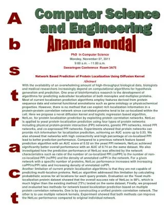
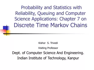
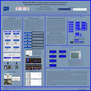
function1() { // some processing layer2_AP=0; layer2_reset=1; // some processing layer2_AP=1; layer2_reset=1; } main() { par // parallel notation { main_operation(); run_time_monitoring(); } } function2() { // some processing layer2_AP=2; layer2_reset=1; // some processing layer2_AP=3; layer2_reset=1; } Run_time_monitoring() { par { Watchdog_layer1(); Watchdog_layer2(); } } main_operation() { function1(); layer1_AP=0; layer1_reset=1; function2(); layer1_AP=1; layer1_reset=1; function3(); layer1_AP=2; layer1_reset=1; } function3() { // some processing layer2_AP=4; layer2_reset=1; // some processing layer2_AP=5; layer2_reset=1; } We seem to be commencing a new era in the embedded logic design, a novel breed of tools, High Level Language Compilers (HLLCs) are entering the market and propose to perform a truly decisive innovation, bridging the gap between software and hardware. Effortless code turn-arounds, faster time to market, increased code readability, System Level Integration are some of the appealing benefits of such tools. What is even promising though is the potential contribution in the design lifecycle. Breathing life into SW/HW co-design can provide the gateway for the introduction of strategic reliability enhancement methods currently utilized in Computer Science such as formal specification, exhaustive verification and structured design principles. The aim of this paper and the associated research project launched in Heriot-Watt University, is to present how High Level Compilers for FPGAs can be combined with proven software methodologies and practices promoting more dependable embedded applications. The product of this work outlined the framework for the development of the Long Range Identification Tag targeting the FPGA Technology and also presented in the document. __ Proof of system liveness Monitoring architecture Monitored system Example of Multi-layered Implementation Watchdog layer2 Fault Tree Analysis - Recovery Strategies The Tag application is composed by a base station controlled by the user and remote stations implanted in inaccessible locations. The base station initiates transmission by broadcasting a command sequence. Selected remote stations respond by transmitting a unique Identification sequence (ID) along with any data required by the base. The time of arrival of the ID is also analyzed to establish tag location. Base station transmission is divided into distinct phases each having different purpose and significance. In the synchronization phase, remote stations are stimulated to exit power-save mode and become synchronized using a variable width modulation scheme. The command sequence is composed by a 16 bit Manchester encoded Return to Zero Scheme with a matrix based forward error correction architecture. __ The development of the tag was based on a structured design methodology in order to enhance system reliability. The lifecycle unfolds around the Spin Model Checker. Spin is considered one of the most efficient software verification tools currently available. It is actively used in safety critical NASA applications such as the mission to Cassini (mission to Saturn) and the Mars Pathfinder. The lifecycle begins with requirements analysis and system specifications description in a graphical method (UML). The core of the application is subsequently designed in the Promela language. In this stage, simulation as well as verification is performed under Spin. The verified Promela model is subsequently translated to HandelC, a C based language for FPGAs and synthesis to gate-level implementation is performed. The finalized HDL/edif is downloaded to the FPGA hardware and system testing is initiated. __ Due to a number of conditions (software or hardware defects) it is possible that an embedded device will hang or deadlock. As this is common in desktop PCs and a user Reset normally resolves the fault, in embedded devices an analogous automated monitoring scheme needs to be constructed. A popular embedded architecture utilized to detect and recover from such faults is Watch Dog Timers (WDTs). WDTs are hardware monitoring structures expecting to be reset by the embedded software in a periodic manner. If the system does not reset the associated WDT in time, a deadlock is assumed and exception handling routines are initiated. Typical recovery strategies for time outs involve re-attempting failed functions or performing a complete system and peripheral reset. WDTs are highly significant in safety critical applications as they form the ultimate line of defence against a system failure. They are used in a wide range of applications ranging from low budget house appliances to high-end safety critical applications. __ SW or HW Mal-operation Watchdog Timer Main controller Reset timer Reset timer Reset timer Fault Begins Propagating into system Reset timer Watchdog layer1 Exceptions on monitoring layers APs utilised for fault location Peripheral / Function reset Exception Handler AP Checker The abstract operation implemented by the system is briefly outlined. A number of languages can be deployed in this phase (UML, CORE, YSM). Watch Dog Timer msecs The higher the complexity of a system the more difficult it is to detect and locate the failure of one of its sub-components. In such applications it is essential that the system is partitioned in blocks or layers and that each of these segments is monitored separately by a dedicated monitoring architecture. Such a scheme can ensure high levels of run-time transparency as well as fault location and isolation. The timed progress watchdog scheme, the monitoring architecture suggested in the project is such a multi-layered implementation. As a potential fault develops and propagates into the system it successively raises exceptions through out the monitoring layers. After a number of exceptions are raised, the exception handler backtracks the sequence of violations pointing out to a specific fault condition ex. a peripheral mal-operation. __ The core of the application is developed in Promela. Simulation under Spin is performed in this phase. In this phase, the design can be examined exhaustively through formal verification. It is checked for deadlock conditions, responsiveness, assertions and mutual exclusion violations. __ Internal Architecture of Monitoring Scheme The Promela model is translated with the aid of Bison and Flex to a language compatible with the Synthesis tools for FPGAs (HandelC). __ Main Input Main Output Synthesis is performed in this stage. The HDL source code is then imported in Xilinx ISE. Generation of configuration file follows. __ Programming of targeted FPGA hardware is performed and system testing takes place. We have attempted to utilise a C Compiler for FPGAs for the development of a commercial application, the Long Range Identification Tag. While there is an ongoing dispute on the optimum design level for FPGAs, we believe that as the targeted hardware evolves (ex. Virtex II Pro FPGAs) and complex systems on chip can be realised, it is becoming increasingly significant to raise the design level exploiting a more familiar and compatible language. __ Assuming that all gate level hazards are managed by the Compiler, the developer is now presented with a new task, verifying the software algorithm rather than the gate level implementation. Towards this process we have applied a set of reliability enhancement strategies including formal verification and run-time monitoring. The Spin Model Checker was utilised to verify protocol correctness (Spin is actively used in NASA applications including the verification of safety critical software for the mission to Cassini and Mar’s Pathfinder). During operation, system liveness is confirmed with the aid of a multi-layered monitoring architecture developed in the C compiler. Gate level Synthesis in DK Suite and system testing on the targeted FPGA follows. __ Developing or formally verifying the protocol in RTL HDL would require at least 3 times the effort focusing mostly on gate level issues and hazards rather than the algorithmic design and testing. Considering the contribution of a C based development process on a number of areas, including productivity, testability and portability we have found the HandelC compiler invaluable for our targeted application. __ Reliable SW/HW Co-Design for Wireless Communication System Integrating the Spin Model Checker and Celoxica's DK Suite Stefanos Skoulaxinos Dept of Engineering and Computer Science, Heriot-Watt University, Edinburgh, UK Special Thanks to Development of Wireless Communication System - LRID Tag Run Time Monitoring and Exception Handling (developed in DK Suite) System Operation Development Lifecycle Monitoring Scheme Watch Dog Timers Multi-Layered Monitoring Tag Location Process Formal Verification of Tag Protocol System View - Base Station System View - Remote Station Operation Remote Station Controller CoolRunner Formal Verification is performed in the Spin Model Checker. Spin is considered one of the most efficient software model checkers currently used in Safety critical mission including NASA’s mission to Cassini (Saturn) and Mar’s Pathfinder. Front End API C Compiler UART Antenna / RF Process Execution Overhead PIC 16F876 PIC 16F876 C Compiler Base Station Functions Vs Time Time modulation • 1 User Selects Tag to be located at front end API • 2 API updates mode of operation of the FPGA via PIC micro-controller • 3 Base Station FPGA initiates RF transmission to remote stations • 4 Base initiates counting - time of arrival of the ID • 5 Selected Remote Station responds by transmitting its unique identification sequence • 6 ID is received at the base. Time of arrival to each of 3 antennas is utilised to compute x,y and z co-ordinates Base Station Controller Spartan IIE/ Spartan3 C Compiler msecs Remote Station Functions Vs Time Antennas / RF Conclusions Reliability Estimation System Testing Reliability Estimated using CASRE (developed by JPL/NASA) Fault Tolerance Disabled MTBF=18 seconds Fault Tolerance Enabled MTBF=50 seconds The research project is a collaboration of School of MACS (Dependable Systems Group) and EPS in Heriot-Watt University, Edinburgh, UK. We would also like to thank the Institute for System Level Integration (ISLI) and Scottish Embedded Software Centre in Livingston. For any information please contact S.Skoulaxinos@hw.ac.uk MAPLD 2005/116 Skoulaxinos