Download
1 / 53
540 likes | 702 Views
Computer Networking TCP/IP Part I. Dr Sandra I. Woolley. Contents. TCP/IP Part 1 The TCP/IP Architecture The Internet Protocol IPv6 Overview TCP/IP Part 2 Transport Layer Protocols Internet Routing Protocols DHCP. The TCP/IP Architecture. Why Internetworking?. Net 1. Net 3. Net 2.

E N D
Computer NetworkingTCP/IP Part I Dr Sandra I. Woolley
Contents • TCP/IP Part 1 • The TCP/IP Architecture • The Internet Protocol • IPv6 Overview • TCP/IP Part 2 • Transport Layer Protocols • Internet Routing Protocols • DHCP
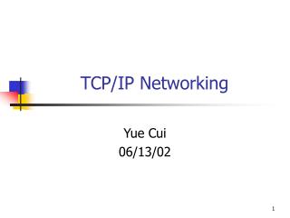
Why Internetworking? Net 1 Net 3 Net 2 Net 5 Net 4 H H G G G G Net 5 Net 5 Net 5 Net 5 Net 5 G G H H • To build a “network of networks” or internet • operating over multiple, co-existing, different network technologies. • providing ubiquitous connectivity. • achieving huge economies of scale.
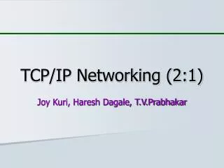
Internet Protocol Approach Transport Layer Network Interface Internet Layer Network Interface Internet Layer Network Interface Network Interface Network Interface Internet Layer Internet Layer Internet Layer Transport Layer Net 1 Net 4 Net 3 Net 2 Host A Router Router Router Net 5 Net 5 Net 5 Net 5 • IP packets transfer information across Internet. Host A IP → router→ router…→ router→ Host B IP • IP layer in each router determines next hop (router). • Network interfaces transfer IP packets across networks. Host B
TCP/IP Protocol Suite SMTP DNS RTP HTTP IP Network Interface 1 Network Interface 3 Network Interface 2 User datagram service Reliable stream service TCP UDP Best-effort connectionless packet transfer (ICMP, ARP) Diverse network technologies
Internet Names Each host has a unique name. Independent of physical location Facilitate memorization by humans Domain Name Organization under single administrative unit Host Name Name given to host computer User Name Name assigned to user Internet Addresses Each IPv4 host has globally unique logical 32 bit IP address. Separate address for each physical connection to a network. Routing decision is done based on destination IP address. IP address has two parts: netid and hostid netid unique and facilitates routing Addresses have a dotted Decimal Notation: e.g., 128.100.10.13 Internet Names and Addresses Reminder DNS resolves IP name to IP address
Physical Addresses Reminder • LANs (and other networks) assign physical addresses to the physical attachment to the network. • The network uses its own address to transfer packets or frames to the appropriate destination. • IP address needs to be resolved to physical address at each IP network interface. • Example: Ethernet uses 48-bit addresses • Each Ethernet network interface controller (NIC) has a globally unique Medium Access Control (MAC) or physical address. • First 24 bits identify NIC manufacturer; second 24 bits are serial number, e.g., • 00:90:27:96:68:07 12 hex numbers Physical MAC addresses are displayed on NICs. ipconfig /all can be used to report the address Intel
Internet Protocol v4 • Provides best effort, connectionless packet delivery. • motivated by need to keep routers simple and for adaptability to failure of network elements. • packets may be lost, out of order, or even duplicated. • higher layer protocols must deal with these, if necessary. • Relevant RFCs are 791, 950, 919, 922, and 2474. • IP is part of Internet STD number 5*, which also includes: • Internet Control Message Protocol (ICMP), RFC 79 * Official RFCs are given STD numbers. IP STD 5 was RFC 791.
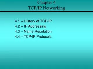
Inside the IPv4 Packet Header 0 4 8 16 19 24 31 Version IHL Type of Service Total Length Identification Flags Fragment Offset Time to Live Protocol Header Checksum Source IP Address Destination IP Address Options Padding bits
Inside the IPv4 Packet Header The header contains from 20-40 bytes as: • Version: current/old IP version is 4. • Internet header length (IHL): length of the header in 32-bit words. • Type of service (TOS): traditionally priority of packet at each router. (Differentiated Services redefines TOS field to include other services besides best effort.) • Total length: number of bytes of the IP packet including header and data. Maximum length is 65535 bytes. • Identification, Flags, and Fragment Offset:used for fragmentation and reassembly.
Inside the IPv4 Packet Header • Protocol: specifies upper-layer protocol that is to receive IP data at the destination. Examples include TCP (protocol = 6), UDP (protocol = 17), and ICMP (protocol = 1). • Header checksum: checks header integrity. • Source IP address and destination IP address: contain the addresses of the source and destination hosts. • Options:Variable length field, allows packet to request special features such as security level, route to be taken by the packet, and timestamp at each router. Detailed descriptions of these options can be found in [RFC 791]. • Padding: This field is used to make the header a multiple of 32-bit words.
IPv4 Header Checksum • IP header uses check bits to detect errors in the header. • A checksum is calculated for header contents. • Checksum recalculated at every router, so algorithm selected for ease of implementation in software. • Let header consist of L, 16-bit words, b0, b1, b2, ..., bL-1 • The algorithm appends a 16-bit checksumbL
IPv4 Checksum Calculation The checksum bL is calculated as follows: • Treating each 16-bit word as an integer, find x = b0 + b1 + b2+ ...+ bL-1 modulo 216-1 • The checksum is then given by: bL = - x modulo 216-1 • This is the 16-bit 1’s complement sum of the b’s • If checksum is 0, use all 1’s representation (all zeros reserved to indicate checksum was not calculated) • Thus, the headers must satisfy the followingpattern: 0 = b0 + b1 + b2+ ...+ bL-1 + bL modulo 216-1
IPv4 Header Processing • Compute header checksum for correctness and check that fields in the header (e.g. version and total length) contain valid values. • Consult the routing table to determine the next hop. • Change the fields that require updating (TTL, header checksum).
IPv4 Addressing • Described in RFC 1166. Each host on the Internet has unique 32 bit IP address. • Each address has two parts: netid and hostid. This facilitates routing. netid is unique • Internet addressing is globally coordinated by the Internet Assigned Numbers Authority (IANA) and delegated to • American Registry for Internet Numbers (ARIN) • Reseaux IP Europeens (RIPE) • Asia Pacific Network Information Centre (APNIC) • African Network Information Center (AfriNIC) • A separate address is required for each physical connection of a host to a network; “multi-homed” hosts. • Dotted-Decimal Notation: • IP address of 10000000 10000111 01000100 00000101 is 128.135.68.5 in dotted-decimal notation.
IPv4 Classful Addresses Class A 7 bits 24 bits hostid netid 1.0.0.0 to 127.255.255.255 0 126 networks with up to 16 million hosts Class B 14 bits 16 bits 128.0.0.0 to 191.255.255.255 hostid 0 netid 1 16,382 networks with up to 64,000 hosts Class C 21 bits 8 bits 192.0.0.0 to 223.255.255.255 0 netid hostid 1 1 2 million networks with up to 254 hosts Class D 28 bits 224.0.0.0 to 239.255.255.255 0 1 1 1 multicast address • Up to 250 million multicast groups
Reserved Host IDs (all 0s & 1s) Internet address used to refer to the network has hostid set to all 0s this host (used when booting up) 0 0 0 0 0 0 a host in this network 0 0 0 host Broadcast address has hostid set to all 1s broadcast on local network 1 1 1 1 1 1 1 1 1 1 1 1 netid broadcast on distant network 1
Private IP Addresses • Specific ranges of IP addresses set aside for use in private networks (RFC 1918) • Use restricted to private internets; routers in public Internet discard packets with these addresses. • Range 1: 10.0.0.0 to 10.255.255.255 • Range 2: 172.16.0.0 to 172.31.255.255 • Range 3: 192.168.0.0 to 192.168.255.255 • Network Address Translation (NAT) used to convert between private & global IP addresses.
Example of IPv4 Addressing 128.140.5.40 128.135.40.1 H Interface Address is 128.135.10.2 Interface Address is 128.140.5.35 H Network 128.135.0.0 Network 128.140.0.0 R H H H 128.135.10.20 128.135.10.21 128.140.5.36 Address with host ID=all 0s refers to the network Address with host ID=all 1s refers to a broadcast packet R = router H = host
Subnet Addressing • Subnet addressing introduces another hierarchical level. • Transparent to remote networks. • Simplifies management of multiple LANs. • Masking is used to find the subnet number.
Subnetting Example • Organization has Class B address (16 host ID bits) with network ID: 150.100.0.0 • Create subnets with up to 100 hosts each • 7 bits sufficient for each subnet • 16-7=9 bits for subnet ID • Apply (AND) subnet mask to IP addresses to find corresponding subnet Example: Find subnet for 150.100.12.176 IP addr. = 10010110 01100100 00001100 10110000 Mask = 11111111 1111111111111111 10000000 AND 10010110 01100100 00001100 10000000 Subnet = 150.100.12.128 Subnet address used by routers within organization.
Subnet Example H1 H2 150.100.12.154 150.100.12.176 150.100.12.128 150.100.12.129 150.100.0.1 R1 To the rest of H3 H4 150.100.12.4 the Internet 150.100.12.55 150.100.12.24 150.100.12.0 150.100.12.1 R2 H5 150.100.15.54 150.100.15.11 150.100.15.0
Routing with Subnetworks • IP layer in hosts and routers maintain a routing table. • Originating host: To send an IP packet, consult routing table. • If destination host is in same network, send packet directly using appropriate network interface. • Otherwise, send packet indirectly; typically, routing table indicates a default router. • Router: Examine IP destination address in arriving packet • If destination IP address not own, router consults routing table to determine next-hop and associated network interface and forwards packet.
Each row in routing table contains: Destination IP address IP address of next-hop router Physical address Statistics information Flags E.g., H indicates target is a host G indicates a gateway/router (i.e. an indirect connection). Routing table search order and action Complete destination address; send as per next-hop and G flag. Destination network ID; send as per next-hop and G flag. Default router entry; send as per next-hop. Declare packet undeliverable; send ICMP “host unreachable error” packet to originating host. Routing Table
Example: Host H5 sends packet to host H2 H1 H2 150.100.12.154 150.100.12.176 150.100.12.128 150.100.12.129 150.100.0.1 R1 To the rest of H3 H4 150.100.12.4 the Internet 150.100.12.55 150.100.12.24 150.100.12.0 150.100.12.1 R2 H5 150.100.15.54 150.100.15.11 150.100.15.0 Routing Table at H5 Destination Next-Hop Flags Net I/F 127.0.0.1 127.0.0.1 H lo0 default 150.100.15.54 G emd0 150.100.15.0 150.100.15.11 emd0 150.100.12.176
Example: Host H5 sends packet to host H2 H1 H2 150.100.12.154 150.100.12.176 150.100.12.128 150.100.12.129 150.100.0.1 R1 To the rest of H3 H4 150.100.12.4 the Internet 150.100.12.55 150.100.12.24 150.100.12.0 150.100.12.1 R2 H5 150.100.15.54 150.100.15.11 150.100.15.0 150.100.12.176 Routing Table at R2 Destination Next-Hop Flags Net I/F 127.0.0.1 127.0.0.1 H lo0 default 150.100.12.4 G emd0 150.100.15.0 150.100.15.54 emd1 150.100.12.0 150.100.12.1 emd0
Example: Host H5 sends packet to host H2 H1 H2 150.100.12.154 150.100.12.176 150.100.12.128 150.100.12.129 150.100.0.1 R1 To the rest of H3 H4 150.100.12.4 the Internet 150.100.12.55 150.100.12.24 150.100.12.0 150.100.12.1 R2 H5 150.100.15.54 150.100.15.11 150.100.15.0 150.100.12.176 Routing Table at R1 Destination Next-Hop Flags Net I/F 127.0.0.1 127.0.0.1 H lo0 150.100.12.176 150.100.12.176 emd0 150.100.12.0 150.100.12.4 emd1 150.100.15.0 150.100.12.1 G emd1
IPv4 Address Problems • In the 1990, two problems became apparent. • IP addresses were being exhausted. • IP routing tables were growing very large. • IP Address Exhaustion • Class A, B, and C address structures were inefficient • Class B was too large for most organizations and rate of allocation suggested exhaustion by 1994. • Class C was too small. • IP routing table size • The growth of the Internet was reflected in the number of table entries. • From 1991 to 1995, routing tables doubled in size every 10 months and stressing router processing power and memory allocation. • Short-term solution: • Classless Interdomain Routing (CIDR), RFC 1518 • New allocation policy (RFC 2050) • Private IP addresses set aside for intranets • Long-term solution: IPv6 with much bigger address space http://arstechnica.com/tech-policy/news/2010/07/internet-will-be-running-on-ipv4-address-fumes-within-a-year.ars
Class A & B assigned only for clearly demonstrated need Consecutive blocks of class C assigned (up to 64 blocks) All IP addresses in the range have a common prefix, and every address with that prefix is within the range Arbitrary prefix length for network ID improves efficiency Lower half of class C space assigned to regional authorities More hierarchical allocation of addresses Service provider to customer New Address Allocation Policy
Supernetting • A “supernet” is a block of contiguous subnetworks addressed as a single subnet. • Summarize a contiguous group of class C addresses using variable-length mask • Example: 150.158.16.0/20 IP Address (150.158.16.0) & mask length (20) IP add = 10010110 10011110 00010000 00000000 Mask = 11111111 1111111111110000 00000000 Contains 16 Class C blocks: From 10010110 1001111000010000 00000000 i.e. 150.158.16.0 Up to 10010110 1001111000011111 00000000 i.e. 150.158.31.0
Classless Inter-Domain Routing • CIDR deals with Routing Table Explosion Problem • Networks represented by prefix and mask • Pre-CIDR: Network with range of 16 contiguous class C blocks required 16 entries • Post-CIDR: Network with range of 16 contiguous class C blocks requires 1 entry • Solution: Route according to prefix of address, not class Routing table entry has <IP address, network mask> Example: 192.32.136.0/21 11000000 00100000 10001000 00000001 min address 11111111 11111111 11111--- -------- mask 11000000 00100000 10001--- -------- IP prefix 11000000 00100000 10001111 11111110 max address 11111111 11111111 11111--- -------- mask 11000000 00100000 10001--- -------- same IP prefix
CIDR Allocation Principles (RFC 1518-1520) • IP address assignment reflects physical topology of network. • Network topology follows continental/national boundaries. • IP addresses should be assigned on this basis. • Routing tables and routing protocols must carry IP address and mask. • Multiple entries may match a given IP destination address. • Example: Routing table may contain • 205.100.0.0/22 which corresponds to a given supernet • 205.100.0.0/20 which results from aggregation of a larger number of destinations into a supernet • Packet must be routed using the more specific route, that is, the longest prefix match • Several fast longest-prefix matching algorithms are available.
Address Resolution Protocol (ARP) H1 H2 H3 H4 150.100.76.22 150.100.76.23 150.100.76.20 150.100.76.21 ARP request (what is the MAC address of 150.100.76.22?) H1 H2 H3 H4 ARP response (my MAC address is 08:00:5a:3b:94) • Although IP address identifies a host, the packet is physically delivered by an underlying network (e.g., Ethernet) which uses its own physical address (MAC address in Ethernet). • How do we map an IP address to a physical address? H1 wants to learn physical address of H3 -> broadcasts an ARP request Every host receives the request, but only H3 replies with its physical address
Reverse Address Resolution Protocol (RARP) • In some situations a host may know its MAC address but not its IP address. This is handled by Reverse Address Resolution Protocol (RARP). • To obtain its IP address, the host broadcasts a RARP request containing its MAC address. Only the server replies with a RARP response containing the host’s MAC and IP addresses.
Fragmentation and Reassembly Source Router Destination IP IP Network Network • Identification field in IP header identifies a particular packet. • Flags = (unused, don’t fragment/DF, more fragment/MF) • Fragment offset identifies the location of a fragment within a packet. Reassemble at destination Fragment at source Fragment at router
Internet Control Message Protocol (ICMP) • RFC 792; Encapsulated in IP packet (protocol type = 1) • Handles error and control messages. • If a router cannot deliver or forward a packet, it sends an ICMP “host unreachable” message to the source. • If a router receives a packet that should have been sent to another router, it sends an ICMP “redirect” message to the sender; Sender modifies its routing table. • ICMP “router discovery” messages allow host to learn about routers in its network and to initialize and update its routing tables. • ICMP echo request and reply can help with fault diagnosis. Used in “ping”.
ICMP Basic Error Message Format 0 8 16 31 Type Code Checksum Unused IP header and 64 bits of original datagram • Type of message: some examples 0 Network Unreachable 3 Port Unreachable 1 Host Unreachable 4 Fragmentation needed 2 Protocol Unreachable 5 Source route failed 11 Time-exceeded, code=0 if TTL exceeded • Code: purpose of message • IP header & 64 bits of original datagram • To match ICMP message with original data in IP packet
Echo Request and Echo Reply Message Format 0 8 16 31 Type Code Checksum Identifier Sequence number Data • Echo request: type=8; Echo reply: type=0 • Destination replies with echo reply by copying data in request onto reply message • Sequence number to match reply to request • ID to distinguish between different sessions using echo services • Used in PING
IPv6 • Longer address field: • 128 bits can support up to 3.4 x 1038 hosts • Simplified header format: • Simpler format to speed up processing of each header • All fields are of fixed size • IPv4 vs IPv6 fields: • Same: Version • Dropped: Header length, ID/flags/frag offset, header checksum • Replaced: • Datagram length by Payload length • Protocol type by Next header • TTL by Hop limit • TOS by traffic class • New: Flow label
Other IPv6 Features • Flexible support for options: more efficient and flexible options encoded in optional extension headers. • Flow label capability: “flow label” to identify a packet flow that requires a certain QoS (Quality-of-Service.) • Security: built-in authentication and confidentiality. • Large packets: supports payloads that are longer than 64 K bytes, called jumbo payloads. • Fragmentation at source only: source should check the minimum MTU along the path. • No checksum field: removed to reduce router packet processing.
IPv6 Header Format 0 4 12 16 24 31 Version Traffic Class Flow Label Payload Length Next Header Hop Limit Source Address Destination Address • Version field same size, same location • Traffic class to support differentiated services • Flow: sequence of packets from particular source to particular destination for which source requires special handling
IPv6 Header Format 0 4 12 16 24 31 Version Traffic Class Flow Label Payload Length Next Header Hop Limit Source Address Destination Address • Payload length: length of data excluding header, up to 65535 bytes • Next header: type of extension header that follows basic header • Hop limit: number of hops the packet can travel before being dropped by a router
IPv6 Addressing • Address Categories • Unicast: single network interface • Multicast: group of network interfaces, typically at different locations. Packet sent to all. • Anycast: group of network interfaces. Packet sent to only one interface in group, e.g. nearest. • Hexadecimal notation • Groups of 16 bits represented by 4 hex digits • Separated by colons • 4BF5:AA12:0216:FEBC:BA5F:039A:BE9A:2176 • Shortened forms: • 4BF5:0000:0000:0000:BA5F:039A:000A:2176 • To 4BF5:0:0:0:BA5F:39A:A:2176 • To 4BF5::BA5F:39A:A:2176 • Mixed notation: • ::FFFF:128.155.12.198
Extension Headers Basic header Next header = TCP segment TCP Basic header Routing header Fragment header Authentication header Next header = Next header = Next header = Next header = TCP segment routing fragment authentication TCP • Extension headers processed in order of appearance Daisy chains of extension headers