Download
1 / 46
890 likes | 2.84k Views
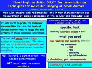
Nuclear Medicine: Tomographic Imaging – SPECT, SPECT-CT and PET-CT. Katrina Cockburn Nuclear Medicine Physicist. Image Acquisition Techniques. Static - (Bones, Lungs) Dynamic - (Renography) Gated - (Cardiac) Tomography SPECT PET List Mode - (Cardiac).

E N D
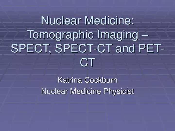
Nuclear Medicine: Tomographic Imaging – SPECT, SPECT-CT and PET-CT Katrina Cockburn Nuclear Medicine Physicist
Image Acquisition Techniques • Static - (Bones, Lungs) • Dynamic - (Renography) • Gated - (Cardiac) • Tomography • SPECT • PET • List Mode - (Cardiac)
Problems with Planar Imaging • Planar imaging • 2D representation of 3D Distribution of activity • No depth information • Structures at different depths are superimposed • Loss of contrast
Problems with Planar Imaging • Planar imaging • 2D representation of 3D Distribution of activity • No depth information • Structures at different depths are superimposed • Loss of contrast
Problems with Planar Imaging • Planar imaging • 2D representation of 3D Distribution of activity • No depth information • Structures at different depths are superimposed • Loss of contrast
Problems with Planar Imaging • Planar imaging • 2D representation of 3D Distribution of activity • No depth information • Structures at different depths are superimposed • Loss of contrast
Problems with Planar Imaging • Planar imaging • 2D representation of 3D Distribution of activity • No depth information • Structures at different depths are superimposed • Loss of contrast
Problems with Planar Imaging • Planar imaging • 2D representation of 3D Distribution of activity • No depth information • Structures at different depths are superimposed • Loss of contrast Image contrast 2:1 Object Contrast 4:1
Single Photon Emission Computed Tomography • Collect multiple planar images at several angles around the patient • Typically 64-128 views over 360° • Can be 32-64 views over 180°
Single Photon Emission Computed Tomography • Image Reconstruction • 2D images of selected planes within the 3D object • Better Contrast • Lower Spatial Resolution • Normal reconstruction techniques are Filtered Back Projection or Iterative Reconstruction
Back Projection • Back Project each planar image onto three dimensional image matrix 3 6 3 3 3 6 6 3 3 3 6 3
Back Projection • Back Project each planar image onto three dimensional image matrix 3 6 3 1 2 1 1 2 1 1 2 1
Back Projection • Back Project each planar image onto three dimensional image matrix 3 6 3 3 2 2 1 3 2 1 2 1 2 1 6 3 4 3 3 2 1 2 3 1 2
Back Projection • Back Project each planar image onto three dimensional image matrix 3 6 3 6 3 4 4 3 6 6 6 8 6 6 3 4 4 3 3 6 3
Back Projection • Back Project each planar image onto three dimensional image matrix 3 6 3 6 3 4 4 3 6 6 6 8 6 6 3 4 4 3 3 6 3
Back Projection • More views – better reconstruction • 1/r blurring, even with infinite number of views
Filtered Back Projection • Filter planar views prior to back projection • Correction of 1/r blurring requires ‘Ramp’ Filter • Gives increasing weight to higher spatial frequencies • Amplifies Noise
Filtered Back Projection • In Practice • Use modifications of Ramp Filter • Compromise between Noise and Spatial Resolution
Modified Ramp Filter • Multiplication of the ramp filter by another function • Often a gaussian shape • Width of the gaussian affects the “roll off” of the ramp
Problems with Filtered Back Projection • Back projection is mathematically correct, but real life images require Filtered Back Projection • Back Projection can introduce noise and streaking artefacts • Not good with attenuation correction • Filtered Back Projection can reduce noise and artefacts, but may degrade resolution
Iterative Reconstruction • NOT a new technique • Pre-dates Filtered Back Projection • Computationally Intensive • Long Reconstruction Times • Requires fast computers for reconstruction • Takes around 1 min for a 16-frame gated 128 x 128 matrix cardiac scan
What is Iterative Reconstruction? • Iteration is process of successively better “guesses” • The image processing computer creates an image by refining the expected projections in comparison to those recorded • This form of IR is known as “Maximum Likelyhood Expectation Maximisation” (MLEM)
Benefits of IR • More accurate modelling of emission/detection • Can include attenuation correction and other information from MR, CT etc • Lower noise
Image Fusion • “Unclear Medicine” images can be registered to CT • Reduces attenuation artefacts • Allows localisation of “fuzzy blob” images • Can improve diagnostic accuracy
Attenuation Correction • X-Ray imaging essentially provides an attenuation “map” • Images formed by different attenuation patterns • NM imaging does not need attenuation • In fact do not want it! • Hybrid imaging (e.g.SPECT-CT) takes attenuation map of CT images and uses to correct for attenuation in 3D NM images
“Jordan” • 6 x 500ml saline bags strapped to torso phantom (3 each side) to simulate breast attenuation • Positioned to cover anterior LV
Normal Perfusion: “Jordan” IRSC FBP FBPSC IR IRAC IRACSC
Resolution Recovery • Resolution worsens with increasing distance from the collimator • If we can model how this happens, we can build this into our Iterative projections
Resolution Recovery • Better modelling means better images • Fewer counts needed to get acceptable images • Shorter acquisitions • Lower doses
NM Imaging: The PET Camera • PET camera invented in the 1970s • Positron Camera 1959
Why use positron emitters? • Many of the positron emitters occur in biological molecules (C, N, O, etc.) • Many have small molecular weights relative to the biological molecules they may be used to label (e.g., F) even if they aren’t found there naturally. • PET isotopes can be attached to biologically interesting molecules with no or minimal impact on the behaviour of those molecules in the body.
Positron Emission Tomography • PET isotopes emit positrons rather than gamma rays • Coincidence Imaging • Better Spatial Resolution (Typically 4mm) • Requires Dedicated Equipment • Limited Availability
Annihilation annihilation photon g conservation of momentum: before: system at rest; momentum ~ 0 after: two photons created; must have same energy and travel in opposite direction. electron/positron annihilation b- b+ annihilation photon conservation of energy before: 2 electrons, each with a rest mass of 511keV after: 2 photons, each with 511keV. g decay via positron emission
Coincidence Imaging line of response (LOR) detector
2D to 3D Imaging • Stack multiple rings behind each other • Allows for true 3D imaging • Shorter imaging time so better throughput and fewer motion artefacts
Because we are “timing” the arrivals of the photons, we can tell how far apart they are All photons travel at the speed of light Simultaneous equation to work out point of origin Makes “line of response” more like a point Time of Flight (TOF) PET
PET Camera Crystals • NaI has too poor stopping power for 511keV • BGO is main material used • Siemens patented LSO *this table was provided by Siemens…