Instructor: Justin Hsia
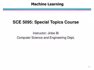
CS 61C: Great Ideas in Computer Architecture MIPS CPU Control, Pipelining. Instructor: Justin Hsia. Hardware Design Hierarchy. system. control. datapath. code registers. state registers. combinational logic. multiplexer. comparator. register. logic. Today. switching networks.

Instructor: Justin Hsia
E N D
Presentation Transcript
CS 61C: Great Ideas in Computer Architecture MIPS CPU Control, Pipelining Instructor: Justin Hsia Summer 2012 -- Lecture #21
Hardware Design Hierarchy system control datapath coderegisters stateregisters combinationallogic multiplexer comparator register logic Today switchingnetworks Summer 2012 -- Lecture #21
Agenda • Quick Datapath Review • Control Implementation • Administrivia • Clocking Methodology • Pipelined Execution • Pipelined Datapath Summer 2012 -- Lecture #21
Datapath Review • Part of the processor; the hardware necessary to perform all operations required • Depends on exact ISA, RTL of instructions • Major components: • PC and Register File (RegFile holds registers) • Instruction and Data Memory • ALU for operations (on two operands) • Extender (sign/zero extend) Summer 2012 -- Lecture #21
ALU 1. Instruction Fetch 1. Instruction Fetch 4. Memory 4. Memory 5. Register Write 5. Register Write 2. Decode/ Register Read 2. Decode/ Register Read 3. Execute 3. Execute Five Stages of the Datapath Register File rd instruction memory PC rs Data memory rt +4 imm MUX Summer 2012 -- Lecture #21
Datapath and Control • Route parts of datapath based on ISA needs • Add MUXes to select from multiple inputs • Add control signals for component inputs and MUXes • Analyze control signals • How wide does each one need to be? • For each instruction, assign appropriate value for correct routing Summer 2012 -- Lecture #21
Addr Instruction Memory MIPS-lite Instruction Fetch nPC_sel zero 4 Instruction Adder 0 32 MUX PC 1 Adder PC Ext CLK imm16 Instr Fetch Unit Summer 2012 -- Lecture #21
1 0 ALU 0 1 MIPS-liteDatapath Control Signals • ExtOp:0 “zero”; 1 “sign” • ALUsrc: 0 busB; 1 imm16 • ALUctr: “ADD”, “SUB”, “OR” • nPC_sel: 0 +4; 1 branch • MemWr: 1 write memory • MemtoReg: 0 ALU; 1 Mem • RegDst: 0 “rt”; 1 “rd” • RegWr: 1 write register nPC_sel Instr Fetch Unit RegDst rd rt CLK ALUctr RegWr rs rt zero 5 5 5 MemtoReg busA 32 MemWr RW RA RB RegFile = busW 32 busB 32 0 32 CLK 32 WrEn Addr Data Memory imm16 Data In 1 Extender 16 32 CLK ALUSrc ExtOp Summer 2012 -- Lecture #21
Agenda • Quick Datapath Review • Control Implementation • Administrivia • Clocking Methodology • Pipelined Execution • Pipelined Datapath Summer 2012 -- Lecture #21
Processor Design Process • Five steps to design a processor: 1. Analyze instruction set datapath requirements 2. Select set of datapathcomponents & establish clock methodology 3. Assemble datapath meeting the requirements 4. Analyze implementation of each instruction to determine setting of control points that effects the register transfer 5. Assemble the control logic • Formulate Logic Equations • Design Circuits Processor Input Now Control Memory Datapath Output Summer 2012 -- Lecture #21
Purpose of Control Instruction<31:0> Instr Memory <0:15> <31:26> <25:21> <20:16> <15:11> <5:0> opcode rs rt rd funct imm16 Controller nPC_sel RegWr RegDst ExtOp ALUSrc ALUctr MemWr MemtoReg Datapath Summer 2012 -- Lecture #21
MIPS-lite Instruction RTL Instr Register Transfer Language adduR[rd]R[rs]+R[rt]; PCPC+4 subuR[rd]R[rs]–R[rt]; PCPC+4 oriR[rt]R[rs]+zero_ext(imm16); PCPC+4 lwR[rt]MEM[R[rs]+sign_ext(imm16)]; PCPC+4 swMEM[R[rs]+sign_ext(imm16)]R[rs]; PCPC+4 beqif(R[rs]==R[rt]) then PCPC+4+[sign_ext(imm16)||00] else PCPC+4 Summer 2012 -- Lecture #21
MIPS-lite Control Signals (1/2) InstrControl Signals adduALUsrc=RegB, ALUctr=“ADD”, RegDst=rd,RegWr,nPC_sel=“+4” subuALUsrc=RegB, ALUctr=“SUB”, RegDst=rd,RegWr, nPC_sel=“+4” oriALUsrc=Imm, ALUctr=“OR”, RegDst=rt, RegWr,ExtOp=“Zero”, nPC_sel=“+4” lwALUsrc=Imm, ALUctr=“ADD”, RegDst=rt, RegWr,ExtOp=“Sign”, MemtoReg, nPC_sel=“+4” swALUsrc=Imm, ALUctr=“ADD”, MemWr, ExtOp=“Sign”, nPC_sel=“+4” beqALUsrc=RegB, ALUctr=“SUB”, nPC_sel=“Br” Summer 2012 -- Lecture #21
MIPS-lite Control Signals (2/2) n/a See MIPS func 10 0000 10 0010 Green Sheet op 00 0000 00 0000 00 1101 10 0011 10 1011 00 0100 add sub ori lw sw beq RegDst 1 1 0 0 X X ALUSrc 0 0 1 1 1 0 MemtoReg 0 0 0 1 X X RegWrite 1 1 1 1 0 0 MemWrite 0 0 0 0 1 0 nPC_sel 0 0 0 0 0 1 Control Signals ExtOp X X 0 1 1 X Add Subtract Or Add Add Subtract ALUctr<2:0> All Supported Instructions • Now how do we implement this table with CL? Summer 2012 -- Lecture #21
Generating Boolean Expressions • Idea #1: Treat instruction names as Boolean variables! • opcode and funct bits are available to us • Use gates to generate signals that are 1 when it is a particular instruction and 0 otherwise • Examples: beq = op[5]’∙op[4]’∙op[3]’∙op[2]∙op[1]’∙op[0]’ Rtype = op[5]’∙op[4]’∙op[3]’∙op[2]’∙op[1]’∙op[0]’ add = Rtype∙funct[5]∙funct[4]’∙funct[3]’ ∙funct[2]’∙funct[1]’∙funct[0]’ Summer 2012 -- Lecture #21
Generating Boolean Expressions • Idea #2: Use instruction variables to generate control signals • Make each control signal the combination of all instructions that need that signal to be a 1 • Examples: • MemWrite = sw • RegWrite = add + sub + ori + lw • What about don’t cares (X’s)? • Want simpler expressions; set to 0! Read from row of table Summer 2012 -- Lecture #21
Controller Implementation • Use these two ideas to design controller: opcode funct RegDst “OR” Logic add “AND” Logic ALUSrc sub MemtoReg ori RegWrite MemWrite lw nPC_sel sw ExtOp beq ALUctr[0] Generate instructionsignals Generate control signals ALUctr[1] Summer 2012 -- Lecture #21
AND Control Logic in Logisim Summer 2012 -- Lecture #21
OR Control Logic in Logisim Summer 2012 -- Lecture #21
lw $t0, 0($2) lw $t1, 4($2) sw $t1, 0($2) sw $t0, 4($2) Great Idea #1: Levels of Representation/Interpretation temp = v[k]; v[k] = v[k+1]; v[k+1] = temp; Higher-Level LanguageProgram (e.g. C) Compiler CALL HOME, WE’VE MADE HARDWARE/SOFTWARE CONTACT!!! Assembly Language Program (e.g. MIPS) Assembler 0000 1001 1100 0110 1010 1111 0101 1000 1010 1111 0101 1000 0000 1001 1100 0110 1100 0110 1010 1111 0101 1000 0000 1001 0101 1000 0000 1001 1100 0110 1010 1111 Machine Language Program (MIPS) Machine Interpretation Hardware Architecture Description(e.g. block diagrams) Architecture Implementation Logic Circuit Description(Circuit Schematic Diagrams) Summer 2012 -- Lecture #20
Agenda • Quick Datapath Review • Control Implementation • Administrivia • Clocking Methodology • Pipelined Execution • Pipelined Datapath Summer 2012 -- Lecture #21
Administrivia • HW 4 due tomorrow • Project 2 due Sunday • No lab on Thursday • Project 3: Pipelined Processor in Logisim Summer 2012 -- Lecture #21
Agenda • Quick Datapath Review • Control Implementation • Administrivia • Clocking Methodology • Pipelined Execution • Pipelined Datapath Summer 2012 -- Lecture #21
Clocking Methodology Clk • Storage elements (RegFile, Mem, PC) triggered by same clock • Critical path determines length of clock period • This includes CLK-to-Q delay and setup delay • So far we have built a single cycle CPU – entire instructions are executed in 1 clock cycle • Up next: pipelining to execute instructions in 5 clock cycles . . . . . . . . . . . . Summer 2012 -- Lecture #21
ALU Register-Register Timing: One Complete Cycle for addu Clk Clk-to-Q Old Value New Value PC Instruction Memory Access Time Rs, Rt, Rd, Op, Func Old Value New Value Delay through Control Logic ALUctr Old Value New Value RegWr Old Value New Value Register File Access Time busA, B Old Value New Value ALU Delay busW Old Value New Value ALUctr RegWr Rd Rs Rt Setup Time 5 5 5 Register Write Occurs Here busA 32 Rw Ra Rb busW 32 RegFile busB 32 clk Summer 2012 -- Lecture #21
ALU Register-Register Timing: One Complete Cycle for addu Clk Clk-to-Q Old Value New Value PC Instruction Memory Access Time Rs, Rt, Rd, Op, Func Old Value New Value Delay through Control Logic ALUctr Old Value New Value RegWr Old Value New Value Register File Access Time busA, B Old Value New Value ALU Delay busW Old Value New Value ALUctr RegWr Rd Rs Rt Setup Time 5 5 5 Register Write Occurs Here busA 32 Rw Ra Rb busW 32 RegFile busB 32 clk Summer 2012 -- Lecture #21
Single Cycle Performance • Assume time for actions are 100ps for register read or write; 200ps for other events • Minimum clock period is? • What can we do to improve clock rate? • Will this improve performance as well? • Want increased clock rate to mean faster programs Summer 2012 -- Lecture #21
Agenda • Quick Datapath Review • Control Implementation • Administrivia • Clocking Methodology • Pipelined Execution • Pipelined Datapath Summer 2012 -- Lecture #21
A B C D Pipeline Analogy: Doing Laundry • Ann, Brian, Cathy, and Dave each have one load of clothes to wash, dry, fold, and put away • Washer takes 30 minutes • Dryer takes 30 minutes • “Folder” takes 30 minutes • “Stasher” takes 30 minutes to put clothes into drawers Summer 2012 -- Lecture #21
2 AM 12 6 PM 1 8 7 11 10 9 30 30 30 30 30 30 30 30 30 30 30 30 30 30 30 30 T a s k O r d e r Time A B C D Sequential Laundry • Sequential laundry takes 8 hours for 4 loads Summer 2012 -- Lecture #21
2 AM 12 6 PM 1 8 7 11 10 9 Time 30 30 30 30 30 30 30 T a s k O r d e r A B C D Pipelined Laundry • Pipelined laundry takes 3.5 hours for 4 loads! Summer 2012 -- Lecture #21
6 PM 7 8 9 Time T a s k O r d e r 30 30 30 30 30 30 30 A B C D Pipelining Lessons (1/2) • Pipelining doesn’t help latencyof single task, just throughputof entire workload • Multipletasks operating simultaneously using different resources • Potential speedup = number of pipeline stages • Speedup reduced by time tofill and drain the pipeline:8 hours/3.5 hours or 2.3X v. potential 4X in this example Summer 2012 -- Lecture #21
6 PM 7 8 9 Time T a s k O r d e r 30 30 30 30 30 30 30 A B C D Pipelining Lessons (2/2) • Suppose new Washer takes 20 minutes, new Stasher takes 20 minutes. How much faster is pipeline? • Pipeline rate limited by slowestpipeline stage • Unbalanced lengths of pipeline stages reduces speedup Summer 2012 -- Lecture #21
Agenda • Quick Datapath Review • Control Implementation • Administrivia • Clocking Methodology • Pipelined Execution • Pipelined Datapath Summer 2012 -- Lecture #21
Recall: 5 Stages of MIPS Datapath 1) IF: Instruction Fetch, Increment PC 2)ID: Instruction Decode, Read Registers 3) EX: Execution (ALU)Load/Store: Calculate AddressOthers: Perform Operation 4) MEM: Load: Read Data from MemoryStore: Write Data to Memory 5) WB: Write Data Back to Register Summer 2012 -- Lecture #21
ALU 1. Instruction Fetch 4. Memory 3. Execute 2. Decode/ Register Read 5. Write Back Pipelined Datapath • Add registers between stages • Hold information produced in previous cycle • 5 stage pipeline • Clock rate potentially 5x faster Register File rd instruction memory PC rs Data memory rt +4 imm MUX Summer 2012 -- Lecture #21
Pipelining Changes • Registers affect flow of information • Name registers for adjacent stages (e.g. IF/ID) • Registers separate the information between stages • At any instance of time, each stage working on a different instruction! • Will need to re-examine placement of wires and hardware in datapath Summer 2012 -- Lecture #21
More Detailed Pipeline • Examine flow through pipeline for lw Summer 2012 -- Lecture #21
Instruction Fetch (IF) for Load Components in use are highlighted For sequential logic, left half means write, right half means read Summer 2012 -- Lecture #21
Instruction Decode (ID) for Load Summer 2012 -- Lecture #21
Execute (EX) for Load Summer 2012 -- Lecture #21
Memory (MEM) for Load Summer 2012 -- Lecture #21
Write Back (WB) for Load There’s something wrong here! (Can you spot it?) Wrong register number! Summer 2012 -- Lecture #21
Corrected Datapath • Now any instruction that writes to a register will work properly Summer 2012 -- Lecture #21
Get To Know Your Staff • Category: Movies Summer 2012 -- Lecture #21
Agenda • Quick Datapath Review • Control Implementation • Administrivia • Clocking Methodology • Pipelined Execution • Pipelined Datapath (Continued) Summer 2012 -- Lecture #21
Time IF ID EX MEM WB IF ID EX MEM WB IF ID EX MEM WB IF ID EX MEM WB IF ID EX MEM WB IF ID EX MEM WB Pipelined Execution Representation • Every instruction must take same number of steps, so some will idle • e.g. MEM stage for any arithmetic instruction Summer 2012 -- Lecture #21
ALU IF ID EX Mem WB 1. Instruction Fetch 4. Memory 3. Execute 2. Decode/ Register Read 5. Write Back I$ D$ Reg Reg ALU Graphical Pipeline Diagrams • Use datapath figure below to represent pipeline: Register File rd instruction memory PC rs Data memory rt +4 imm MUX Summer 2012 -- Lecture #21
Time (clock cycles) I n s t r O r d e r I$ Reg ALU Load D$ Reg I$ Add ALU D$ Reg Reg I$ Reg ALU Store D$ Reg D$ Reg Sub ALU I$ Reg I$ D$ Reg ALU Or Reg Graphical Pipeline Representation • RegFile: right half is read, left half is write Summer 2012 -- Lecture #21
Instruction Level Parallelism (ILP) • Pipelining allows us to execute parts of multiple instructions at the same time using the same hardware! • This is known as instruction level parallelism • Recall: Types of parallelism • DLP: same operation on lots of data (SIMD) • TLP: executing multiple threads “simultaneously” (OpenMP) Summer 2012 -- Lecture #21