Download
1 / 34
340 likes | 491 Views
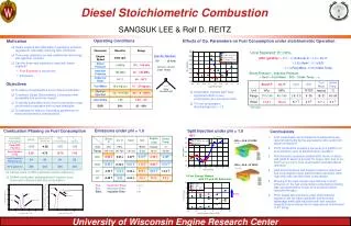
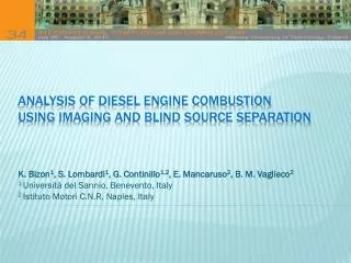
Analysis of diesel engine combustion using imaging and blind source separation . K. Bizon 1 , S. Lombardi 1 , G. Continillo 1,2 , E. Mancaruso 2 , B. M. Vaglieco 2 1 Università del Sannio , Benevento, Italy 2 Istituto Motori C.N.R , Naples , Italy. Introduction

E N D
Analysis of diesel engine combustion using imaging and blind source separation K. Bizon1, S. Lombardi1, G. Continillo1,2, E. Mancaruso2, B. M. Vaglieco2 1 Università del Sannio, Benevento, Italy 2 Istituto Motori C.N.R, Naples, Italy
Introduction Experimentalsetup & procedure Independentcomponentanalysis Analysisofcrank-angleresolvedmeasurements Cycle-to-cyclevariationsanalysis Comparisonwithothermethods Summary & conclusions Outline
First attempt of application of independent component analysis (ICA) to 2D images of combustion-related luminosity acquired from an optically accessible Diesel engine • Identificationof the leadingindependentstructures (independentcomponents, ICs) and: • study of the transient behavior of the flame during a single cycle • analysis of the cycle-to-cycle variability • Assessment of the alternative decompositions (e.g. proper orthogonal decomposition, POD) Objectiveof the work
The fast development of optical systems has made available measurements of distributed in-cylinder variables but the measurements interpretation is not always easy due to the huge amount of data, and to the variety of coupled phenomena taking place in the combustion chamber This has lead to the increasing interest in the application of sophisticated mathematical tools, e.g. proper orthogonal decomposition (POD) has become a popular reduction and analysis tool. It has contributed to the knowledge of many physical phenomena, but it cannot separate independent structures,i.e.all POD modes contain some element of all structures found in all of the fields Alternative decompositions can be considered, e.g. independent component analysis (ICA) can be expected to provide a more powerful insight with respect to POD Introduction
Introduction Experimentalsetup & procedure Independentcomponentanalysis Analysisofcrank-angleresolvedmeasurements Cycle-to-cyclevariationsanalysis Comparisonwithothermethods Summary & conclusions Outline
Direct injection four-stroke diesel engine with a single cylinder and a multi-valve production head The research engine features only two valves and utilizes a classic extended piston with a UV grade crown window ExperimentalEngine
High-speed digital complementary metal oxide semiconductor (CMOS) camera, controlled by a trigger signal generated by a delay unit linked to the engine encoder, in combination with a 45° UV/visible mirror located inside the piston OPTICAL setup
Engine speed of 1000 rpm, continuous-mode operation, using commercial Diesel fuel Injection pressure fixed at 600 bar and no EGR Typical CR injection strategy of pre, main and post injections (PMP) starting at -9°, -4° and 11° CA with duration of 400, 625 and 340 μs Cylinder pressure recorded at 0.1 CA° increments by means of a pressure transducer ROHR calculated using the first law, perfect gasapproach CMOS high-speed camera: frame rate of 4 kHz and exposure timeof 166 μs 888 images of the in-cylinder luminosity field, collected from -4° to 30.5° CA, with CA increment of 1.5°, over N= 37 consecutive fired cycles The original spatial mesh of 529×147 is clipped to 120×120 pixels framing the combustion chamber Experimental procedure & REsults
Introduction Experimentalsetup & procedure Independentcomponentanalysis Analysisofcrank-angleresolvedmeasurements Cycle-to-cyclevariationsanalysis Comparisonwithothermethods Summary & conclusions Outline
POD vs. ICA Properorthogonaldecompositon • Extracts dominant structures - orthonormal and optimal in the L2 sense • Relatively simple eigenvalue problem to solve • Fields of application: turbulent flows, model reduction, image processing, PIV data & flame luminosity from SI & Diesel engines Independentcomponentanalysis • Extracts a set of mutually independent signals from the mixture of signals, i.e. permits to separate the data into underlying informational components • Optimization problem maximizing some measure of the independence • Fields of application: neuroimaging, spectroscopy, combustion engines (separation of vibration sources)
POD vs. ICA Properorthogonaldecompositon • Extracts dominant structures - orthonormal and optimal in the L2 sense • Relatively simple eigenvalue problem to solve • Fields of application: turbulent flows, model reduction, image processing, PIV data & flame luminosity from SI & Diesel engines Independentcomponentanalysis • Extracts a set of mutually independent signals from the mixture of signals, i.e. permits to separate the data into underlying informational components • Optimization problem maximizing some measure of the independence • Fields of application: neuroimaging, spectroscopy, combustion engines (separation of vibration sources)
Given: : randomvectoroftemporalmixtures : temporal (mutuallyindependent) source signals The mixing model can bewrittenas: Ifthenmatrixisinvertible and the model can berewrittenas: The ICA problemconsistofcalculatingsuchthatisanoptimalestimationof ICA problem can be solved by maximization of the statistical independence of the estimates ICA: Definition
Maximizationofnongaussianity(“nongaussianisindependent”) • Maximizationofkurtosis (e.g. a fast-pointalgorithmusingkurtosiscalledFastICA) • Maximizationofnegentropy (normalizedversionofdifferential information entropy) • Minimizationofmutual information • Maximumlikelihoodestimation • Tensorialmethods • Nonlineardecorrelation and nonlinear PCA ICA: approaches
FastICA algorithm maximizes non-gaussianityby means of a gradient method. The (non-)gaussianity is estimated by the absolute value of kurtosis defined as: The algorithm is employed on centered (having zero mean) and whitened data (uncorrelated and have unit variances), i.e.: - raw data - POD eigenvectors - POD eigenvalues (on the diagonal) If the number of ICs is smaller than the number mixtures, the data can be reduced during the whitening using leading POD modes ICA: FastICAalgorithm
ICA: separationofimagemixture independentcomponents POD modes sources separation mixing mixtures
Introduction Experimentalsetup & procedure Independentcomponentanalysis Analysisofcrank-angleresolvedmeasurements Cycle-to-cyclevariationsanalysis Comparisonwithothermethods Summary & conclusions Outline
PMP at -9°, -4° and 11° CA cranK angle resOlvedmeasurEments combustion present on all jets and in the vicinity of the chamber wall main injection combustion first luminous spots due to ignition of the preinjected fuel combustion zone moves towards the bowl wall Images of combustion luminosity for multiple injections in a cycle, at several crank angles simultaneous ignition of postinjection jets maximum of post combustion luminosity
ICA: Cycle 8 y1 y2
ICA: Cycle 9 y1 y2
Analysisof ICS and theircoefficients y1: combustion along the fuel jets; swirl motion y2: combustion near the chamberwalls y1 y2 y1 y2 2° CA 5° CA 9.5° CA 2° CA 5° CA 9.5° CA
ICS vs. Engineparameters 3.5° CA 17° CA maximum luminosity of the regular combustion process near the fuel jets of the main and post injection main inj. post inj. SOC of PMP: –4°, 1° & 14° CA 8° CA
Introduction Experimentalsetup & procedure Independentcomponentanalysis Analysisofcrank-angleresolvedmeasurements Cycle-to-cyclevariationsanalysis Comparisonwithothermethods Summary & conclusions Outline
Not all jets burn with the same flame behavior; during combustion development flames are unevenly distributed along the jets’ axes Post injection starts in a partly burning environment, where the irregular peripheral combustion influences post-injection ignition Cycle-to-cyclevariations main injection combustion 2° CA 3.5° CA end of main combustion; post injection 14° CA 18.5° CA post injection combustion
ICA separates the mean combustion luminosity at each CA from the irregular flame structure related to cycle variability 3.5°cA
Separation is worse when the variability is higher, i.e. at the end of main combustion when the flames move randomly near the bowl wall 14°cA
Again, the separation is better when the cyclic variability is lower, i.e. for the CA characterized by regular combustion typical of jet burning 18.5°cA
a1peakswhere an irregular combustion process takes place (less effective separation) and is low when the burning along the jets dominates CV of a2 is at least one order of magnitude higher than the CV of a1, confirming that strong deviations from the ideal combustion process are located near the bowl wall ICS vs. Engineparameters pilot injection fuel burning in the centre of the bowl random flames near the bowl regular burning of the main & post injection fuel along the jet directions irregular end of combustion
Introduction Experimentalsetup & procedure Independentcomponentanalysis Analysisofcrank-angleresolvedmeasurements Cycle-to-cyclevariationsanalysis Comparisonwithothermethods Summary & conclusions Outline
ICA vs. POD Independentcomponents POD modes Negentropy, i.e. normalizeddifferential information entropy, measures the amountof information and isalwayshigherfor ICA thanfor POD; itisestimatedas:
Analysis of cycle variations (but not crank angle resolved measurements!) similar conclusions for the first two statistical moments (mean & standard deviation) Here the "signals" were, in most cases, already spatially separated ICA vs. 1st and 2nd moment Independentcomponents 1st and 2nd moment Cycyle-to-cyclevariations Crank angle resolvedmeasurments
Introduction Experimentalsetup & procedure Independentcomponentanalysis Analysisofcrank-angleresolvedmeasurements Cycle-to-cyclevariationsanalysis Comparisonwithothermethods Summary & conclusions Outline
A first attempt of the application of ICA to luminosity image data collected in an optical engine was done • Two independent components were found related to: • combustion along the fuel jets presenting low variability over the cycles • near the bowl walls – highly variable; this confirms quantitatively that strong deviations from the ideal combustion process are located near the bowl walls • The analysis is fast and reliable - a single computation takes less than 0.1 s on a standard sequential single processor • Benefits of ICA can be much higher than this simple application example shows. Based on the demonstration case, more complex data can be analyzed, and what was presented here is a first and convincing example of how ICA works in an engine context Summary & conclusions
From the movie L’Atalanteby Jean Vigo (1932) Dita Parlo (bornasGerda Olga JustineKornstädt on 4th Sept 1908 in Szczecin, Poland