Download
1 / 26
260 likes | 412 Views
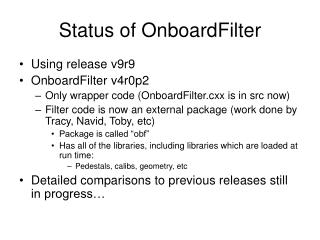
Graphite Target. beam. 1st Horn. 2nd Horn. 3rd Horn. I=320kA. Status of horns. A.K.Ichikawa. Activities. T. Sekigutchi joined the target-horn group. US group (E.D.Zimmerman, J.Spitz, L.Bartoszek) have contributed on beam MC study, design of horns. Other contributions by T. Nakadaira,

E N D
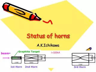
Graphite Target beam 1st Horn 2nd Horn 3rd Horn I=320kA Status of horns A.K.Ichikawa
Activities • T. Sekigutchi joined the target-horn group. • US group (E.D.Zimmerman, J.Spitz, L.Bartoszek) have contributed on beam MC study, design of horns. • Other contributions by T. Nakadaira, S. Tada, Y. Yamada, S. Koike, Y. Suzuki, T. Kobayashi et al.
Overview of Target Station Supporting points Concrete shield(1m) Iron Shield (2.2m) Iron structure (= helium vessel) supports horns and shields
Beam MC study by J. Spitz • J.Spitz’s report is available at http://jnusrv01.kek.jp/jnu/tgt-horn/beamMC • Effects of mis-alignment -> Covered at the last collab.meeting • Effects of the horn current drop • Effects of beam angle deflection • Possible beam plug at 4MW
On-axis Peak Energy Effects of Horn1 current drop -3% Flux at Super-K 0 -1 -2 -3 -4 -5 -6 -7 -8 -9 -10 % -3% Off-axis Peak Energy -0.5% 0 -1 -2 -3 -4 -5 -6 -7 -8 -9 -10 % 0 -1 -2 -3 -4 -5 -6 -7 -8 -9 -10 %
1st horn and 3rd horn • Design and production of prototype is on going toward the current operation test.
Design of the 1st horn peripherals • Done by BARTOSZEK Engineering • Water seal (EVAC, helicoflex) • Water pipe • Auxiliary drain • Galvanic corrosion • Stripline heat load • etc. etc. etc. • Production of them and assembling was contracted and to be completed at March.
Striplines locate far from horn body to reduce heat load from radiation Setup for the test operation. Striplines are extended downward for the test.
Water Nozzle attachment-water tightness, insulation and galvanic corrosion- Stainless flange Helicoflex seal Ceramic disk to insulate outer-conductor and water-pipes Aluminum knife-edge seal for water seal Outer-conductor Nozzle head
Stripline Forced He cooling is necessary to cool heat load from radiation. Clamp to resist the Lorenz force is designed not to prevent He flow. Stress w/ Lorenz force 9.3MPa
Outer-conductor contracted • Ceramic ring (f1430mm!) contracted
Water system pumping up 7m in ultra-high radiation environment -two options- Self priming canned motor pump Test will be done soon with canned motor pump option. 7m Ejector pump
Support module 75mm thick plate Pipes and supporting shafts go through this plate. Rigidity is the issue to achieve 1mm alignment Here, we will have remote connection mech. for support, pipes and striplines.
FEM analysis by S. Koike Distortion is <0.3mm. (Tolerance of the horn alignment is 1mm.) Strong enough for earthquakes and (unexpected) 2-points crane hanging. Radiation level calculation by Y. Oyama.-> not fully satisfactory but maybe acceptable. We plan to make prototype in next FY.
Support module Alignment mech. Kinematic mount on leveling block on xy-stage. X,Y,Z position can be adjusted with freedoms to absorb manufacturing errors. When the module installed remotely by crane, it can positioned automatically while absorbing manufacturing errors.
Dummy load(4ton) It works well!
Hot Lab. Remote disconnection/connection from this level • Lift table • It must be controlled remotely. • On the lift table, there are x and y stages.
Summary • Schedule • Continue Design and R&D in FY2006 • Current operation test, support module, remote handling etc. etc. • Produce everything in FY2007 • Installation in FY2008
セラミックスリング:納入済み 外部導体:納入済み 内部導体:納入済み セラミックスワッシャーとセラミックスボルトチューブ:納入済み
Alignment of (e) part of the new horn will be done at the Dock using a spare support box, on which alignment of (a) and (c) are already done. We assume that it will be valid with the existing support box. Spare support box New horn
1st horn and 2nd horn 3rd horn Only (b) has an re-adjustable mechanism. Other parts will be fixed once it is adjusted. (a) and (c) : correct manufacturing error of the support box. (b) correct target station He chamber distortion. (d) guide mechanism between the support box and horn frame. (e) correct manufacturing error of the horn frame. (a) (b) (c) (d) (e) Remote coupling here for easy access from the top level.