Download
1 / 31
320 likes | 534 Views
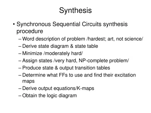
XST Synthesis. FPGA Design Workshop. Objectives. After completing this module, you will be able to…. List the synthesis options for XST Describe how to insert code from the Language Template Specify various methods for entering constraints. Xilinx Design Process. Step1 : Design

E N D
XST Synthesis FPGA Design Workshop
Objectives After completing this module, you will be able to… • List the synthesis options for XST • Describe how to insert code from the Language Template • Specify various methods for entering constraints
Xilinx Design Process • Step1: Design • Two design entry methods: HDL(Verilog or VHDL) or schematic drawings • Step2: Synthesize to create Netlist • Translates V, VHD, SCH files into an industry standard format EDIF file • Step 3: Implement design (netlist) • Translate, Map, Place & Route • Step 4: Configure FPGA • Download BIT file into FPGA HDL code Schematic Synthesize Netlist Implement BIT File
XST Synthesis in Project Navigator • Module/entity selected in Sources window treated as “top” • XST-specific processes • Synthesize • View Synthesis Report • Analyze Hierarchy • Check Syntax • XST-specific properties • Synthesis Options • HDL Options • Xilinx Specific Options AM2910 as top-level
Device Support FPGAs Virtex Virtex-E Virtex-II Virtex-II Pro Spartan-II Spartan-IIE CPLDs XC9500 XC9500XL XC9500XV CoolRunner CoolRunner-II XST provides technology specific optimization for:
XST Flow VHDL Verilog Constraints Synthesis Technology Specific Optimization To Implementation Tools Synthesis Report File .NGC .LOG
Main Synthesis Steps HDL HDL ParsingIdentification of language syntax errors HDL SynthesisMacro recognition, FSM extraction,resource sharing Low Level OptimizationMacro implementation, timing optimization,LUT mapping, register replication .NGC .LOG
ISE GUI • Synthesis options • Global synthesis and optimization goal and effort • HDL options • Family-specific inference and optimization options • Xilinx Specific options • Specific low-level implementation and optimization algorithms
XST: Synthesis Options • Set global synthesis, optimization goal, and effort • Optimization Goal (speed/area) • Optimization Effort (normal/high) • Synthesis Constraints File • Any text file • Use Synthesis Constraints File • Global Optimization Goal • Generate RTL Schematic • Write Timing Constraints • Verilog 2001
XST: HDL Options • Set family-specific inference and optimization options • FSM Encoding Algorithm • RAM/ROM/Multiplexer Extraction • RAM/Multiplexer Style • Decoder/Priority Encoder Extraction • Shift Register/Logical Shifter Extraction • XOR Collapsing • Resource Sharing • Complex Clock Enable Extraction
XST: Xilinx-Specific Options • Set specific low-level implementation and optimization algorithms • Add I/O Buffers • Maximum Fanout • Equivalent Register Removal • Register Balancing • Move First/Last Flip-Flop Stage • Slice Packing • Pack I/O Registers into IOBs
Language Templates • Two methods to open templates: • Language Icon • Edit -> Language Templates • Language Templates provide common templates for designs: • Component instantiation • Language templates • Synthesis templates
Language Templates • To use template, be sure that an HDL source file is already opened • Place cursor at the location for the code to be entered • In the Language Template GUI, right-click on the template you wish to use • Select “Use in…” • Be sure the appropriate file name is listed
What are Constraints? • Writing constraints is a method of communicating your design and performance objectives to the synthesis tools and implementation tools
Xilinx Design Process • Step1: Design • Two design entry methods: HDL(Verilog or VHDL) or schematic drawings • Step 2: Synthesize to create Netlist • Translates V, VHD, SCH files into an industry standard format EDIF file • Step 3: Implement design (netlist) • Translate, Map, Place & Route • Step 4: Configure FPGA • Download BIT file into FPGA HDL code Schematic Synthesize Synthesis CONSTRAINTS Netlist Implementation CONSTRAINTS Implement BIT File
XST Constraints • XST will accept synthesis constraints through the Xilinx Constraints File (XCF) • Do not confuse this with the User Constraints File (UCF), which contains implementation constraints for the Xilinx tools • When using an XCF file, specify the file in the Synthesis Options tab
XST Constraints • To quickly enable or disable the use of a constraint file by XST, you can check or uncheck the Use Synthesis Constraint File menu -uc -iuc
XCF - MODEL • To apply a constraint to the entire entity or module, use the following syntax: MODEL entity_name constraint_name = constraint_value; Note: If a constraint is applied to an entity or module, the constraint will be applied to each instance of the entity/module • To apply constraints to specific instances or signals within an entity or module, use the INST or NET keywords: BEGIN MODEL entity_name INST instance_name constraint_name = constraint_value; NET signal_name constraint_name = constraint_value; END;
Design Constraints FF3 FF1 FOE FF3 F0E3 FF1 F0E1 • If XST decides to push flip-flops to IOBs, then the following cases are taken into account • Flip -flops controlling OBUFTs will be replicated
Design Constraints reg reg reg reg reg • Flip-flops having feedback will be replicated A RES CLK A CLK RES IOB=TRUE
Design Constraints • If the output flip-flop belongs to a shift register and represents its last stage, then it will be pushed to an IOB • Note: XST will not reduce the number of stages in SRL and infer additional flip-flops in order to improve the clock-to-out of the slice • Example: If the user has described a 16-bit shift register, then: RESULT Generated by XST SLICE IOB=TRUE SLICE SI SRL 14 bit RES IOB=TRUE reg reg SI SRL 15 bit RES reg CLK CLK
How XST Identifies Critical Paths During Timing Optimization FF FF • Notes • Other synthesis tools apply frequency specification to all four regions • ALLCLOCKNETS (the default constraint for timing optimization) in XST represents only clock-to-clock regions • MAX_DELAY is the constraint incorporating all four regions. Allclocknets Period Offset_in_Before Offset_out_After logic logic IPAD OPAD IPAD logic Inpad_to_Outpad OPAD IPAD
How XST Identifies Critical Paths During Timing Optimization • The identification of a critical path depends on the timing constraints and is based on the slack calculation • The value of the slack depends on the way the constraints are applied • As soon as all of the slacks are identified, XST will choose the smallest (most negative) one in order to identify the Critical Region • Let us consider the following example
How XST Identifies Critical Paths During Timing Optimization • Suppose we have two clocks (clk1, clk2) in the design. Before timing optimization their periods are estimated as: • clk1 : 30 ns • clk2 : 25 ns • If no value is supplied with the ALLCLOCKNETS constraint, XST will calculate the slack assuming the goal delay is 0 ns: • clk1 : -30 ns • clk2 : -25 ns • As a consequence, clk1 will be considered the critical one and XST will try to optimize this clock first
How XST identifies Critical Paths During Timing Optimization • Suppose a PERIOD constraint defines individual timing requirement for each clock: 25 ns for clk1, 15 ns for clk2. In this case the slack will be: • clk1 : -5 ns • clk2 : -10 ns • As a result, clk2 will be considered the critical one, and XST will try to optimize this clock first • The ultimate goal, in both cases, is to increase the slack of all paths within the Critical Region. However, the final results of optimization are directly affected by the types and values of the constraints applied
Understanding the Log File • The log file can be divided into three main parts: HDL Compilation HDL Analysis Table of synthesis options HDL Synthesis Messages generated duringsynthesis Low LevelSynthesis Final report General Statistic Table Timing Report
Log File Organization TABLE OF CONTENTS 1) Synthesis Options Summary 2) HDL Compilation 3) HDL Analysis 4) HDL Synthesis 4.1) HDL Synthesis Report 5) Low Level Synthesis 6) Final Report 6.1) Device utilization summary 6.2) TIMING REPORT . . . ========================================================================= * HDL Compilation * ========================================================================= Compiling vhdl file constant.vhd in Library my_lib. . . . ========================================================================= * HDL Synthesis * ========================================================================= Synthesizing Unit <led_dec>. . . .
Messages During Synthesis • The structure of this part directly reflects the main steps of the synthesis • Lists files used during • synthesis • Syntax check Warnings • and Errors HDL Compilation ... HDL Analysis • Information on extracted • macros and FSMs for • each hierarchical block • Summary Table on extracted macros for the entire design • Encoding style chosen for each FSM Messages generatedduring synthesis HDL Synthesis Low LevelSynthesis ... • Information on register • replication and removal
Final Report ... Messages generated during synthesis GeneralStatistic Table Final Report Timing Report (FPGA only)
Timing Report • XST is trying to keep its post-synthesis timing report close to the report generated by TRACE • Moreover, we have added a new table at the beginning of the report summarizing clock information of the design • List of all clocks in the design • How each clock is bufferized • How many loads each clock has
Summary • XST is provided with v5.2i ISE software • XST provides various options for synthesizing designs • Language Templates allow you to re-use commonly used code • Several methods for entering constraints