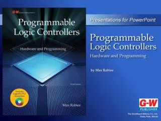
PLC Timer Instructions
8. PLC Timer Instructions. Objectives. Use non-retentive and retentive timer ON-delay instructions to create PLC ladder logic diagrams. Use move (MOV) instructions to create variable preset value timer instructions. Use OFF-delay timers to create PLC ladder logic diagrams. Objectives.


PLC Timer Instructions
E N D
Presentation Transcript
8 PLC Timer Instructions
Objectives • Use non-retentive and retentive timer ON-delay instructions to create PLC ladder logic diagrams. • Use move (MOV) instructions to create variable preset value timer instructions. • Use OFF-delay timers to create PLC ladder logic diagrams.
Objectives • Connect timer instructions to interlock each other. • Cascade timer instructions in a PLC ladder logic diagram to increase the timer preset values.
Timers • Fixed timers • Variable timers • Single-input timers • Double-input timers
Timer Instructions • In the relay logic diagrams, symbols are used to represent timer coils and their associated timer contacts.
Timer Instructions (Cont.) • Two types of timer instructions: • ON-delay timers. • OFF-delay timers.
ON-delay Timers • Start timing when timer coils are energized. • Normally open contacts close and normally closed contacts open when the timer is finished timing. • Contacts immediately revert to normal states when the timer accumulated register resets to zero. • Delay before contacts switch when timer turns on; no delay in switching when timer turns off.
OFF-delay Timers • Start timing when their timer coils are de-energized. • Normally open contacts close and normally closed contacts open when the timer is finished timing. • Contacts revert to their normal states when the timer accumulated register resets to zero.
Timer Instruction Formats • Coil format: • Uses coils to display the timer instruction. • Block format: • Uses a box shape to display the timer instruction. • More common symbol for displaying timer instructions.
PLC Timer Instruction Registers • Preset register: • Contentis the preset value that the timer is initialized to hold. • Holds the preset number. • Accumulated register: • Holds the time that the timer has been timing. • Status register,also called flag register: • Holds the flag bits that are used by the PLC processor to monitor the status of the timer.
PLC Timer Instruction Registers (Cont.) • Timers in Allen-Bradley SLC 500 series PLC: • Data file four (T4)reserved for timer instructions. • Timers have addresses T4:0 to T4:255. • In theory, can have up to 256 timers. • In practice, number of timers is limited by PLC memory capacity.
Timer Base Number • Multiplied by the preset number. • Defines unit of time as a fraction of a second or a second. • 0.01 seconds, 0.1 seconds, and 1 second most commonly used in PLC timers.
Timing Bits • Enable bit (EN) • Timer timing bit (TT) • Done bit (DN)
PLC Timer Instruction Timers • Three different types of timers for Allen-Bradley SLC 500 series PLCs: • Non-retentive timer ON-delay. • Retentive timer ON-delay. • Non-retentive timer OFF-delay.
Fixed Preset Value Non-retentive Timer ON-Delay Instructions • Block diagram of an SLC 500 non-retentive timer ON-delay with address T4:0.
Variable Preset Value Non-retentive Timer ON-Delay Instructions • Move (MOV) instruction: • Used for copying the content of one register into another or for loading a number into a register. • Can be used to create a variable preset timer.
Retentive Timer ON-Delay Instructions • Reset (RES) instruction: • Used to reset a retentive timer.
Timer OFF-Delay Instructions • PLC ladder logic diagram using timer off-delay.
Interlocking Timers • Interlocked timers: • Outputturns on and off sequentially. • Common method of flashing lights or ringing bells in Allen-Bradley SLC 500 series programmable logic control systems.
Interlocking Timers (Cont.) • PLC ladder logic diagram using two timers.
Cascading Timers • In some industrial applications: • Timers must have a large preset value. • PLC ladder diagrams that contain several timers can be created. • Cascadinglinks multiple timers together.
Cascading Timers (Cont.) • Timers are cascaded together such that when one timer is finished timing, the second one starts. • When the second timer is done, the third one starts, and so forth.