Download
1 / 32
320 likes | 417 Views
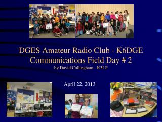
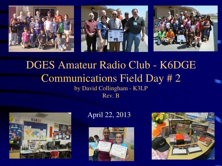
DGES Amateur Radio Club - K6DGE Communications Field Day # 2 by David Collingham - K3LP Rev. B. April 22, 2013. Communications Field Day # 2. AGENDA Introduction (5 Minutes) Re-Fresh & Practice Operating Techniques (10 Minutes) Student Teams; 3 Teams with 10 Students each:

E N D
DGES Amateur Radio Club - K6DGECommunications Field Day # 2by David Collingham - K3LPRev. B April 22, 2013
Communications Field Day # 2 • AGENDA • Introduction (5 Minutes) • Re-Fresh & Practice Operating Techniques (10 Minutes) • Student Teams; 3 Teams with 10 Students each: • - Module A; Students Getting on the Air; K6DGE Station (40 Minutes, Each Team) • - Module B; Building Amateur Radio Antennas; Vertical Versus Dipole/Inverted Vee (40 Minutes, • Each Team) • - Module C; Electronics Theory and Lab (40 Minutes, Each Team)
Communications Field Day # 2 15 Minutes 40 Minutes 40 Minutes 40 Minutes Module B - Antenna Building Team 1 Module B - Antenna Building Team 3 Module B - Antenna Building Team 2 Module C; Electronics Theory & lab Team 2 Module C; Electronics Theory & lab Team 1 Module C; Electronics Theory & lab Team 3 Introduction Re-Fresh & Practice Operating Techniques Lunch Module A- Students Getting on the Air; K6DGE Station Team 3 Module A- Students Getting on the Air; K6DGE Station Team 2 Module A- Students Getting on the Air; K6DGE Station Team 1 10:20 AM 11:20 AM 12:15 PM 2:30 PM
Introductions Instructor(s) and Participants: Beverly Matheson (KJ6SRX) Louis P. Malory (WA6DVK) David Collingham (K3LP) Dr. Arnold Shatz (N6HC) Charles Spetnagel (W6KK) Clark Stewart (W8TN) Jay Kobelin (W2IJ) Mike Mitchell (W6RW)
Re-Fresh & Practice Operating Techniques Getting Set-Up to Transmit • Get on the correct Frequency (Band Permission), select needed Mode (i.e. SSB, CW, AM or RTTY) and make sure correct transmit power is being used: • USB = Upper Side Band • LSB = Lower Side Band • AM = Amplitude Modulation • CW = Continuous Wave • Check to make sure Frequency is not in use before CQing. • “ QRZ is this Frequency in use?”
Re-Fresh & Practice Operating Techniques APPROACH FOR CALLING CQ & MAKING A QSO CQ CQ THIS IS K6DGE Kilowatt Six Delta Gulf Ecco CQ CQ THIS IS K6DGE Kilowatt Six Delta Gulf Ecco CQ CQ THIS IS K6DGE Kilowatt Six Delta Gulf Ecco Calling CQ and Waiting for a Call “STATIONS CALL SIGN” THIS IS K6DGE THANK YOU MUCH FOR YOUR CALL. MY NAME IS XXXXXX. MY QTH IS FONTANA, CALIFORNIA YOUR REPORT IS 59 MY AGE IS XX MY RADIO IS ICOM IC-746PRO, 100 Watts MY ANTENNA IS VERTICAL SO HOW COPY? “STATIONS CALL SIGN” THIS IS K6DGE OVER
Re-Fresh & Practice Operating Techniques(continued) COMMON USED “Q” CODES AND ABBREVATIONS QRL = Are you busy? I am busy, please do not interfere QRM = Is my transmission being interfered with? Your transmission is being interfered with QRN = Are you troubled by static? I am troubled by static ___ QRP= Shall I decrease power? Decrease power. QRT = all I stop sending? Stop sending. QRZ = Who is calling me? You are being called by ___. QSB = Are my signals fading? Your signals are fading. QTH = What is your location? My location is ___. QSL = Can you acknowledge receipt? I am acknowledging receipt. QSO = Can you communicate with ___? I can communicate with ___) QSY = Shall I change to another frequency? Change to another frequency. 73’s = Best Wishes 88’s = Hugs and Kisses OM = OLD MAN XYL = WIFE YL = YOUNG LADY
Re-Fresh & Practice Operating Techniques(continued) SIGNAL REPORT (RST) Readability; 1-5 (1 little Copy and 5 Clear Copy) Signal Strength; 1-9 (1 weak and 9 Strong) Tone; 1-9 (1 Poor Tone/Stability & 9 Good Tone & Stable)
Module A- Students Getting on the Air; K6DGE Station • Each Student Gets an Opportunity to Call CQ Twice and Complete a QSO when possible. (10 Students in team x 4 minutes each = 40 minutes) • Rotate Students; One person Calling CQ, 2nd student Logging QSO’s in K6DGE Logbook, and remaining students listening for call signs and record QSO information • Students get to practice making QSO’s and learn how to communicate and exchange radio related information and using proper communications techniques
Module B; Build Amateur Radio Antennas; Vertical Versus Dipole/Inverted Vee • Discuss differences between the following antennas: • - 1/4 Wave Vertical Antenna • - 1/4 Wave Dipole Antenna • - Inverted Vee Antenna • Divide Team (10) into two groups of 5 • Half of the Team will make a 1/4 Wave Dipole for 15 Meters (21.300 Mhz) • Half of the Team will make a 1/4 Wave Vertical for 20 Meters (14.245 Mhz) • Each Team will test their antenna on-the-air to make sure SWR (Standing Wave Ratio) is less than 1.5:1
Module B; Build Amateur Radio Antennas; Vertical Versus Dipole/Inverted Vee Example: Antenna Feed Point
Module B; Build Amateur Radio Antennas; Vertical Versus Dipole/Inverted Vee Vertical versus Dipole Signal Pattern
Module B; Build Amateur Radio Antennas; Vertical Versus Dipole/Inverted Vee Dipole Signal Pattern
Module B; Build Amateur Radio Antennas; Vertical Versus Dipole/Inverted Vee Vertical Signal Pattern
Module B; Build Amateur Radio Antennas; Vertical Versus Dipole/Inverted Veecontinued MAKING & TESTING A 15 Meter 1/4 Wave Dipole Antenna • Half of the Team will make a 1/4 Wave Dipole for 15 Meters (21.300 Mhz) • Each Team will test their antenna on-the-air to make sure SWR (Standing Wave Ratio) is less than 1.5:1 FORMULA for 1/2 Wave in Feet = 468/F Mhz 468/21.300 = 21.97’ or 21’ 11 5/8” 21.97’ x 0.5 = 10.485’ or 10’ 5 6/8” 10’ 5 6/8” 10’ 5 6/8”
Module B; Build Amateur Radio Antennas; Vertical Versus Dipole/Inverted Veecontinued MAKING & TESTING A 20 Meter 1/4 Wave Vertical Antenna • Half of the Team will make a 1/4 Wave Vertical Antenna for 20 Meters (14.245 Mhz). Qty 1 1/4 Wave Vertical Radial and Qty 3 1/4 Wave Ground Radials. • Each Team will test their antenna on-the-air to make sure SWR (Standing Wave Ratio) is less than 1.5:1 FORMULA for 1/2 Wave in Feet = 468/F Mhz 468/14.245 = 32.85’ or 32’ 10 /4” 16’ 5 1/8” 32.85’ x 0.5 = 16.425’ or 16’ 5 1/8” 16’ 5 1/8” x 3 Places
Module B; Build Amateur Radio Antennas; Vertical Versus Dipole/Inverted Veecontinued Checking the Antenna SWR SWR stands for standing wave ratio. It measures how much power is being applied to the antenna versus how much of that power is being reflected back to the radio. Too much reflected power can damage the power amplifier of the radio. This reflected power can be caused by a number of things; broken or loose connections, coax with the improper characteristic impedance, problems with the antenna, etc. However, the most common problem is the feed point of an antenna is higher or lower than the 52 ohm impedance of the coax. This is caused either because the antenna is too long or short or the impedance matching circuit (if it has one at all) is not adjusted properly.
Module C - Electronics Theory and Lab • Materials; Non-Conductive and Conductive • Voltage; Direct Current (DC) • Voltage; Alternating Current (AC) • Discuss Electronic Components and Symbols: • - Wire • - Resistors • - Capacitors • - Inductors • Using a Digital Volt-Ohm Meter (VOM)
Module C - Electronics Theory and Lab • Materials; Non-Conductive and Conductive • Materials; Non-conductive: • - Glass • - Plastic • - Rubber • - Insulator (non-metal) • - Wood • Materials; Conductive: • - Gold • - Copper • - Aluminum • - Salt water
Module C - Electronics Theory and Lab • Voltage; Direct Current (DC) and Alternating Current Battery; 1.5 VDC, 9 VDC, 12 VDC Typical House Outlet: 120 VAC
Module C - Electronics Theory and Lab • Voltage; Direct Current (DC) • Direct Current (DC): Direct current or DC electricity is the continuous movement of electrons from an area of negative (−) charges to an area of positive (+) charges through a conducting material such as a metal wire. Whereas static electricity sparks consist of the sudden movement of electrons from a negative to positive surface, DC electricity is the continuous movement of the electrons through a wire. A DC circuit is necessary to allow the current or steam of electrons to flow. Such a circuit consists of a source of electrical energy (such as a battery) and a conducting wire running from the positive end of the source to the negative terminal. Electrical devices may be included in the circuit. DC electricity in a circuit consists of voltage, current and resistance. The flow of DC electricity is similar to the flow of water through a hose.
Module C - Electronics Theory and Lab • Voltage; Direct Current (DC) • Direct Current (DC); Series and Parallel Circuits
Module C - Electronics Theory and Lab • Voltage; Alternating Current • Alternating Current (AC): AC is short for alternating current. This means that the direction of current flowing in a circuit is constantly being reversed back and forth. This is done with any type of AC current/voltage source. The electrical current in your house is alternating current. This comes from power plants that are operated by the electric company. Those big wires you see stretching across the countryside are carrying AC current from the power plants to the loads, which are in our homes and businesses. The direction of current is switching back and forth 60 times each second.
Module C - Electronics Theory and Lab • Voltage; Alternating Current • Alternating Current (AC): 1 AC Cycle Formulas: Time (T) = 1/f Frequency (f) = 1/T 0.016667 Seconds or 60 Hz Low Frequency Medium Frequency Higher Frequency
Module C - Electronics Theory and Lab Radio Waves and Frequency versus Wavelength The Speed of Light = 299, 792,458 miles/second Formula: Velocity (wave) : Radio waves go through far more cycles in a second than electric current, and we need to use bigger designation units to measure them. We have chosen to use the metric system for such designations. One is the kilohertz (kHz), which is equal to 1000 cycles per second. Another common one is the megahertz (MHz), which is equal to 1,000,000 cycles per second, which is the equivalent of also 1000 kHz. A gigahertz (GHz) is 1000 megahertz. The obvious relationship between these units is typical of metric designation changes, being a factor of 1000. 1,000,000 Hertz = 1000 Kilohertz = 1 Megahertz = .001 Gigahertz
Module C - Electronics Theory and Lab Radio Waves and Frequency versus Wavelength The Speed of Light = 299, 792,458 miles/second or 300,000,000 Wavelength (Meters) = 300/Freq. (Mhz) Most common Amateur Radio Bands and Frequencies: 10 Meters = 300/30 (28.0 thru 30 Mhz) 15 Meters = 300/20 (21.0 thru 21.4 Mhz) 20 Meters = 300/15 (14.0 thru 15 Mhz) 40 Meters = 300/7.5 (7.0 thru 7.5 Mhz) 75 Meters = 300/4.0 (3.75 thru 4.0 Mhz) 80 Meters = 300/3.75 (3.5 thru 3.75 mhz) 160 Meters - 300/1.875 (1.8 thru 1.9 Mhz)
Module C - Electronics Theory and Lab OHMS LAW • Ohm's law states that the current through a conductor between two points is directly proportional to the potentialdifference across the two points. Introducing the constant of proportionality, the resistance, one arrives at the usual mathematical equation that describes this relationship: • where I is the current through the conductor in units of amperes, V is the potential difference measured across the conductor in units of volts, and R is the resistance of the conductor in units of ohms. More specifically, Ohm's law states that the R in this relation is constant, independent of the current. • The law was named after the German physicist GeorgOhm, who, in a treatise published in 1827, described measurements of applied voltage and current through simple electrical circuits containing various lengths of wire. He presented a slightly more complex equation than the one above to explain his experimental results. The above equation is the modern form of Ohm's law.
Module C - Electronics Theory and Lab OHMS LAW - Calculator
Module C - Electronics Theory and Lab • Discuss Electronic Components and Symbols: • - Resistors:A resistor "Resists electricity. Think of it as a restriction in a water pipe only for electricity. • - Capacitors: A capacitor (originally known as condenser) is a passive two-terminal electricalcomponent used to store energy in an electricfield. The forms of practical capacitors vary widely, but all contain at least two electricalconductors separated by a dielectric (insulator); for example, one common construction consists of metal foils separated by a thin layer of insulating film. Capacitors are widely used as parts of electricalcircuits in many common electrical devices. • - Inductors: An inductor (also choke, coil, or reactor) is a passive two-terminal electricalcomponent that stores energy in its magneticfield. For comparison, a capacitor stores energy in an electricfield, and a resistor does not store energy but rather dissipates energy as heat. • Any conductor has inductance. An inductor is typically made of a wire or other conductor wound into a coil, to increase the magnetic field. • When the current flowing through an inductor changes, a time-varying magnetic field is created inside the coil, and a voltage is induced, according to Faraday’slawofelectromagneticinduction, which by Lenz'slaw opposes the change in current that created it. Inductors are one of the basic components used in electronics where current and voltage change with time, due to the ability of inductors to delay and reshape alternating currents.
Module C - Electronics Theory and Lab • Examples of Electronic Components Resistors: Resistor Symbol:
Module C - Electronics Theory and Lab • Examples of Electronic Components Capacitors: Inductors:
Module C - Electronics Theory and Lab • Using a Volt-Ohm Meter (VOM) Digital Volt-Ohm Meter (VOM) Analog Volt-Ohm Meter (VOM)