Download
1 / 56
560 likes | 636 Views
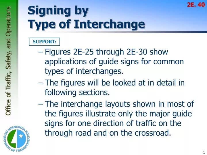
2E. 40. Signing by Type of Interchange. Figures 2E-25 through 2E-30 show applications of guide signs for common types of interchanges. The figures will be looked at in detail in following sections.

E N D
2E. 40 Signing byType of Interchange • Figures 2E-25 through 2E-30 show applications of guide signs for common types of interchanges. • The figures will be looked at in detail in following sections. • The interchange layouts shown in most of the figures illustrate only the major guide signs for one direction of traffic on the through road and on the crossroad.
2E. 40 Signing byType of Interchange • The signing layout for all interchanges having only one exit ramp in the direction of travel should be similar, regardless of the interchange type. • For the sake of uniform application, the significant features of the signing plan for each of the more frequent kinds of interchanges (illustrated in Figures 2E-27 through 2E-38) should be followed as closely as possible. • Even when unusual geometric features exist, variations in signing layout should be held to a minimum.
2E.41 Freeway-to-FreewayInterchange • Freeway-to-Freeway interchanges are major decision points where the effect of taking a wrong ramp cannot be easily corrected. • Reversing direction on the connecting freeway or re-entering to continue on the intended course is usually not possible.
2E.41 Freeway-to-FreewayInterchange • Sign messages should contain only the route marker, cardinal direction, and the name of the next control city on the route. • At splits where the off-route movement is to the left or where there is an optional lane split, diagrammatic signs should be used at the Advance Guide Sign location.
2E.41 Freeway-to-FreewayInterchange • Overhead signs shall be used at a distance of 1 mile and at the theoretical gore of each connecting ramp. • Overhead signs may also be used at the ½ mile and 2 mile points. • The arrow and/or control city may be omitted on signs that indicate the straight-ahead continuation of a route.
2E.41 Freeway-to-FreewayInterchange • Figure 2E-27
2E.42 Cloverleaf Interchange • A cloverleaf interchange has two exits for each direction of travel • The exits are closely spaced and have common Advance Guide Signs
2E.42 Cloverleaf Interchange • The AG signs should include two place names, one corresponding to each ramp, with the name of the place served by the first exit on the upper line
2E.42 Cloverleaf Interchange • Overhead signs shall be placed at the theoretical gore point of the first exit ramp, with an upward slanting arrow on the Exit Direction sign and the message XX MILE on the AG sign for the second exit.
2E.42 Cloverleaf Interchange • The second exit shall be indicated by an OH Exit Direction sign over the auxiliary lane. • An Exit sign shall also be used at each gore. • Diagrammatic signs shall NOT be used.
2E.42 Cloverleaf Interchange • Figure 2E-28 • The Exit Direction sign for the second exit should be mounted on the structure if the mainline passes under the crossroad
2E.43 Cloverleaf Interchangewith C-D Roadways • Signing on the collector-distributor roadways should be the same as the signing on the mainline of a cloverleaf interchange. • Guide signs at exits from the collector-distributor roadways shall be overhead and located at the theoretical gore of the collector-distributor roadway and the exit ramp.
2E.43 Cloverleaf Interchangewith C-D Roadways • Figure 2E-29
6-7.02.03 Auxiliary Lane Signing • This section outlines uniform signing standards for auxiliary lanes on freeways, with and without escape lanes. • The following layouts should be used in the appropriate situation. • Auxiliary lane less than 1/2 mile in length, without escape lane (See Figure 6.29A). • Auxiliary lane less than 1/2 mile in length, with escape lane (See Figure 6.29B). • Auxiliary lane 1/2 mile in length or greater, without escape lane (See Figure 6.29C). • Auxiliary lane 1/2 mile in length or greater, with escape lane (See Figure 6.29D).
6-7.02.03 Auxiliary Lane Signing • Figure 6.30A (< ½ mi w/o escape)
6-7.02.03 Auxiliary Lane Signing • Figure 6.30B (< ½ mi with escape)
6-7.02.03 Auxiliary Lane Signing • Figure 6.30C (> ½ mi w/o escape)
6-7.02.03 Auxiliary Lane Signing • Figure 6.30D (> ½ mi with escape)
2E.44 Partial Cloverleaf Interchange • Typical application of guide signs for partial cloverleaf interchanges is shown in Figure 2E-30.
2E.44 Partial Cloverleaf Interchange • As shown in Figure 2E-30, the overhead Exit Direction sign should be placed on the structure if the mainline passes under the crossroad and the exit roadway is located beyond the structure.
2E.45 Diamond Interchange • The typical diamond interchange ramp departs from the mainline roadway such that a speed reduction generally is not necessary in order for a driver to safely negotiate an exit maneuver from the mainline onto the ramp roadway. • When a speed reduction is not necessary, an exit speed sign should not be used.
2E.45 Diamond Interchange • The Exit Speed sign should be located along the deceleration lane or along the ramp such that it is visible to the driver far enough in advance so that a safe slowing and exiting maneuver can be made.
2E.45 Diamond Interchange • A Stop Ahead or Signal Ahead warning sign may be placed, where engineering judgment indicates a need, along the ramp in advance of the cross street, to give notice to the driver (see Section 2C.26). • When used on two-lane ramps, Stop Ahead or Signal Ahead signs should be used in pairs with one sign on each side of the ramp.
2E.45 Diamond Interchange • Figure 2E-31
2E.46 Diamond Interchangein an Urban Area • A typical application of guide signs for diamond interchanges in an urban area is shown in Figure 2E-32. • This example includes the use of the Community Interchanges Identification sign (see Section 2E.38) which might be useful if two or more interchanges serve the same community. • In urban areas, street names are often shown as the principal message in destination signs.
2E.46 Diamond Interchangein an Urban Area • Figure 2E-32
2E.46 Diamond Interchangein an Urban Area • If interchanges are too closely spaced to properly locate the Advance Guide signs, they may be placed closer to the exit, and the distance figures adjusted accordingly.
2E.47 Closely-Spaced Interchanges • When a series of interchanges is closely spaced, the advance guide sign for the next interchange may be mounted on an overhead structure located downstream from the gore of the preceding interchange. • Interchange Sequence signs should be used at closely spaced interchanges. • When used, they should identify and show street names and distances for the next two or three exits as shown in Figure 2E-23.
2E.47 Closely-Spaced Interchanges
2E.47 Closely-Spaced Interchanges • Advance Guide signs for closely spaced interchanges shall show information for only one interchange.
2E.48 Minor Interchange • At least one Advance Guide sign and an Exit Gore sign shall be placed at a minor interchange. • An Exit Direction sign should also be used.
2E.48 Minor Interchange • Figure 2E-33
2E.49 Signing of Approachesand Connecting Roadways • The freeway or expressway signing standards should be extended to the approach roadways because conventional guide signing on the approach roads, as described in Chapter 2D, might in some cases be ineffective for some of the more important interchanges. • Guide signing for frontage roads should be consistent with the requirements for freeways and expressways.
2E.49 Signing of Approachesand Connecting Roadways • Consistently applied signing for conventional road approaches to freeway or expressway interchanges is highly desirable.
2E.49 Signing of Approachesand Connecting Roadways • The signing of conventional roads with one lane of traffic approaching an interchange should consist of a sequence containing the following signs: • Junction Assembly • Destination Sign • Directional Assembly or Entrance Direction Sign for the first ramp • Advance Route Turn Assembly or Advance Entrance Direction Sign with an advance arrow turn • Directional Assembly or Entrance Direction Sign for the second ramp
2E.49 Signing of Approachesand Connecting Roadways • Figure 2E-34
2E.49 Signing of Approachesand Connecting Roadways • Figure 6.26 • unsignalized
2E.49 Signing of Approachesand Connecting Roadways • Figure 6.27 • signalized
2E.49 Signing of Approachesand Connecting Roadways • At minor interchanges, the following sequence of signs may be used: • Junction Assembly • Directional Assembly for the first ramp • Directional Assembly for the second ramp
2E.49 Signing of Approachesand Connecting Roadways • Figure 2E-35
2E.49 Signing of Approachesand Connecting Roadways • On multi-lane conventional roads approaching an interchange, the sign sequence should contain the following signs: • Junction Assembly • Advance Entrance Direction Sign(s) for both directions (if applicable) of travel on the freeway or expressway • Entrance Direction Sign for first ramp • Advance Route Turn Assembly • Entrance Direction Sign for the second ramp
2E.49 Signing of Approachesand Connecting Roadways • Figure 2E-36
2E.49 Signing of Approachesand Connecting Roadways • Figure 2E-37
2E.49 Signing of Approachesand Connecting Roadways • Figure 2E-38
2E.50 Wrong-Way Traffic Controlat Interchange Ramps • At interchange exit ramp terminals where the ramp intersects a crossroad in such a manner that wrong-way entry could inadvertently be made, the following signs shall be used: • At least one ONE WAY sign for each direction of travel on the crossroad shall be placed where the exit ramp intersects the crossroad. • At least one DO NOT ENTER sign shall be conspicuously placed near the end of the exit ramp in positions appropriate for full view of a road user starting to enter wrongly.
2E.50 Wrong-Way Traffic Controlat Interchange Ramps • At least one WRONG WAY sign shall be placed on the exit ramp facing a road user traveling in the wrong direction.
2E.50 Wrong-Way Traffic Controlat Interchange Ramps • Figure 2E-39
2E.50 Wrong-Way Traffic Controlat Interchange Ramps • In addition, the following pavement markings should be used: • On two-lane paved crossroads at interchanges, double solid yellow lines should be used as a centerline for an adequate distance on both sides approaching the ramp intersections. • Where crossroad channelization or ramp geometrics do not make wrong-way movements difficult, a lane use arrow should be placed in each lane of an exit ramp near the crossroad terminal where it will be clearly visible to a potential wrong-way road user.
2E.50 Wrong-Way Traffic Controlat Interchange Ramps
2E.50 Wrong-Way Traffic Controlat Interchange Ramps • The following traffic control devices may be used to supplement the above signs and pavement markings: • Additional ONE WAY signs may be placed, especially on two-lane rural crossroads, appropriately in advance of the ramp intersection to supplement the existing ONE WAY sign(s). • Additional WRONG WAY signs may be used.