Download
1 / 13
130 likes | 331 Views
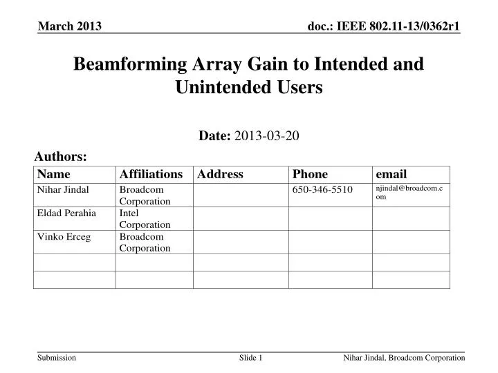
Beamforming Array Gain to Intended and Unintended Users. Date: 2013-03-20. Authors:. Introduction. In this presentation we show array gain experienced by intended and unintended users Unintended user typically sees significantly lower array gain than the intended user because:

E N D
Beamforming Array Gain to Intended and Unintended Users Date: 2013-03-20 Authors: Nihar Jindal, Broadcom Corporation
Introduction • In this presentation we show array gain experienced by intended and unintended users • Unintended user typically sees significantly lower array gain than the intended user because: • Beamforming weights are matched to the intended user’s channel • Any difference between intended/unintended users’ channels reduces array gain at unintended user • Unintended and intended user’s channels are different due to different multipath propagation Nihar Jindal, Broadcom Corporation
Array Gain Computation • Draw channel to intended user & form BF vectors based on this channel • Draw channel to unintended user • Unintended user’s channel may have different statistics than intended, e.g., different delay spread or K factor • Array gain = RX power at unintended user with BF on versus with no BF • RX power is averaged over 20 MHz Nihar Jindal, Broadcom Corporation
Channel Models • Channel models from Jagganatham-Erceg paper [1] • Intended user (indoors): exponential PDP with spike with 6.3 dB spike + LoS component on 1st tap • 14 nsec/7.5 dB are median values for delay spread/K factor for 1st tap for LOS co-polar at 3 meters (plotted below) • 13 nsec/11.7 dB are 90% values for delay spread/K factor for 1st tap for LOS co-polar at 3 meters • Because shorter delay spread yields more array gain, 90% value for delay spread is chosen at 10% point of CDF (smaller than median) • Unintended user (outdoors): 100 nsecrms delay spread, 0 dB K factor on 1st tap, no spike [2] Nihar Jindal, Broadcom Corporation
Results for Nt=2/3/4/6/8 • Using median values for delay spread/K factor and 90% point of multipath array gain Nihar Jindal, Broadcom Corporation
Results for Nt=2/3/4/6/8 • Using 90% values for delay spread/K factor and 50% point of multipath array gain Nihar Jindal, Broadcom Corporation
Summary of Results • Considerably smaller array gain with 90 % delay spread/K-factor and 50% point of multipath compared to 50% delay spread/K-factor and 90% point of multipath • With either choice of parameters array gain seen is considerably smaller than maximum value of 10log10(Nt) Median values for delay spread/K factor and 90% point of multipath array gain 90% values for delay spread/K factor and median values for multipath array gain Nihar Jindal, Broadcom Corporation
Conclusion • In this presentation we show that beamforming array gain is reduced to the unintended user because of different propagation channel • For 4 transmit antenna case gain reduction is in the 2-3.4 dB range, depending on the statistical analysis method applied Nihar Jindal, Broadcom Corporation
References • [1] Aditya K. Jagannatham and Vinko Erceg, “MIMO Indoor WLAN Channel Measurements and Parameter Modeling at 5.25 GHz”, IEEE 60th Vehicular Technology Conference, 2004, VTC2004-Fall., Vol. 1, 26-29 Sep'04, Pages:106 - 110, Vol. 1. • [2] Mark E. Beach, Matthew W. Webb, and Carmen Stan, “Virtual MIMO performance in a measured outdoor-to-indoor cellular scenario”, Antennas and Propagation (EUCAP), Proceedings of the 5th European Conference, 11-15 April 201, Pages: 2933 – 2937. Nihar Jindal, Broadcom Corporation
Appendix Nihar Jindal, Broadcom Corporation
Sensitivity to delay spread • Nt = 4, Intended user has 6.3 dB spike + 7.5 dB K factor on 1sttap, and unintended user has 0 dB K factor on 1st tap, no spike • Blue: vary delay spread of intended user while keeping unintended user delay spread equal to 100 nsec • Green: vary delay spread of unintended user while keeping intended user delay spread equal to 14 nsec • Increasing delay spread of intended or unintended user significantly reduces array gain • This illustrates the importance of properly modeling the channel statistics to intended/unintended user, e.g., indoor/outdoor Nihar Jindal, Broadcom Corporation
Sensitivity to K-factor • Nt = 4, Intended user has 14 nsecrms delay spread and 6.3 dB spike on 1sttap, and unintended user has 100 nsecrms delay spread and no spike • Blue: vary K-factor of intended user while keeping unintended user K-factor equal to 0 dB • Green: vary K-factor of unintended user while keeping unintended user K-factor equal to 7.5 dB • Increasing K factor of intended or unintended user increases array gain, although not considerably beyond nominal values of 7.5/0 dB K factor to intended/unintended Nihar Jindal, Broadcom Corporation
Median vs. 90% Values • Blue: Median rms delay spread and K-factor, 90% point for multipath • Green: 90% values for rms delay spread and K-factor, 50% point for multipath • Median K-factor with 90% multipath array gain gives 3.7 dB array gain, whereas 90% K-factor with 50% multipath array gives only 2.6 dB Nihar Jindal, Broadcom Corporation