Download
1 / 25
250 likes | 498 Views
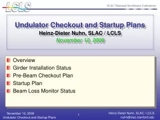
Undulator Checkout and Startup Plans Heinz-Dieter Nuhn, SLAC / LCLS November 12, 2008. Overview Girder Installation Status Pre-Beam Checkout Plan Startup Plan Beam Loss Monitor Status. LCLS Installation and Commissioning Time-Line. Install Undulators. First Light in FEH.

E N D
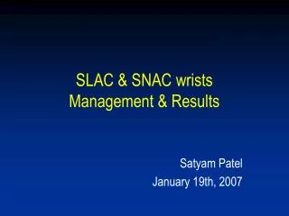
Undulator Checkout and Startup PlansHeinz-Dieter Nuhn, SLAC / LCLSNovember 12, 2008 • Overview • Girder Installation Status • Pre-Beam Checkout Plan • Startup Plan • Beam Loss Monitor Status 1
LCLS Installation and Commissioning Time-Line InstallUndulators First Light in FEH PPS Cert. LTU/Dump LTU/Und Install X-Rays in NEH First Light in FEE CD-4 (7/31/2010) FEE/NEH Install FEH Hutch BO PEP-II run ends now J F M A M J J A S O N D J F M A M J J A S O N D J F M A M J J D M D A 2008 2009 2010 Down Down? PPS LTU/Und Comm. NEH Ops & Commissioning Linac/BC2 Commissioning Re-establish e- to SL2 FEL/FEE Commissioning Nov. 3, 2008 2
Undulator Checkout and Startup • Installation (=>Nov 08) • All beamline components except Undulator Segments • Initial Checkouts (=>Nov 08) • Quads/Corrs, BFWs, RFBPMs, Girder Motion, Control System, ADS • Correction of problems found during Initial checkouts (Nov 08) • Broken BFW wires, Girder Motion Issues, Quad Terminal Corrosion, etc • Conventional Alignment (Nov 08) • Set all cams to “Home Position” and disable girder motion control • Align quadrupoles to “straight line” within 100 um (rms) • Center BFWs between quadrupoles. • Final Pre-Beam Checkouts. Checklist exists (200+ pp). (Nov-Dec 08) • Magnet Polarities / Motion (Girder, BFW, Slide) etc. • Pre-Undulator Commissioning with Beam (Jan 09 – Mar 09) • Motion Control / Beam Containment / Beam-Based Alignment / etc. • Installation of Undulator Segments (Mar 09) • Undulator Commissioning with Beam (Mar 09 – Apr 09) • Beam Based Alignment / Undulator Slide Functions / Beam Stability 3
Girder Component Alignment and Girder Installation Component Alignment on CMM Girders installed in Undulator Hall 4
Girder Installation Status All girders are installed! Alignment of all girder components (including “test” undulator segment) has been checked and corrected (if necessary) on CMM. All quadrupoles have been individually characterized before installation All BFW devices have been thoroughly tested for reproducibility before installation. Problems repeatability problems excist Tuning and fiducialization of undulator segment is on-going. Reminder: First Installation of undulator segments on girder planned for March 2009. 5
BFW Positioning Beam travels out of slide plane 6
Correction of Problems found during Initial Checkouts • Replacement of 3 BFW cards that had broken wires[done] • Correction of quadrupole terminal plate corrosions • Correction of Interface Plate alignment to avoid cam block motion restriction • Improvement mounting of linear potentiometers for cam motion control [done] • Cam motion trouble shooting 7
Findings Requiring Correction Insufficient area for linear pot Quad terminal corrosion Uneven reference for linear pot Broken BFW wires 8
Undulator Pre-Beam Checkout List: Overview • Checkout Items per Girder • BFW • BLM • CAM ROTATIONS • LINEAR POTENTIONMENTERS • GIRDER MOTION • HORIZONTAL SLIDES • QUADRUPOLE, XCOR, YCOR • RF-BPM • TEMPERATURE SENSORS • WPM AND HLS SENSORS 10
Undulator Beamline Commissioning to Main Dump with Beam but without Undulator Segments (Jan-Mar 08) • Get Beam through Undulator vacuum pipe with minimum losses. • Commission Radiation Monitors • Checkout BPMs (timing, scale, sign errors, etc.) • Commission Girder Motion with Beam • Verify and calibrate steering effect of quadrupole motion • Calibrate motion parameters (gain, pivot points etc.) • Check BPM offset tracking • Commission RF Cavity BPMs • Check charge dependent response over entire charge range • Use Girder Motion to calibrate position vs. readings • Check and correct optics matching over entire operational energy range • Commission Beam Based Alignment (BBA) • Develop saved configurations for three different energies. • Commission BBA GUIs and BBA procedure. • Commission Beam Finder Wires • Calibrate PMT signals. • Commission BFW GUIs (Alignment and scanning capabilities) • Commission ADS-based girder position stabilization feedback systems. • Commission Tune-Up Dump in preparation for commissioning with Undulator Segments 13
Install Undulator Segments (Mar 09) • Mount Undulator Segments onto girdersSegments will be stored in Undulator Hall before installation • System is designed to be Self-Aligning • Re-check slide motion clearance • Expect to install 3 Segments / day Segment installation test scheduled for week of 11/18/2008 14
First Beam Through Undulator Segments (Mar 09) • Conditions for First Beam: • All Undulator Magnets Rolled-Out • Single Shot Operation (low charge) • Send single electron bunch through undulator • Read and evaluate as much diagnostics as possible along undulator(such as BPMs, beam loss monitors, toroids) • Identify and remove sources of beam loss – if any • Iterate • Goal: Get beam through vacuum chamber with minimum losses. • Reminder: Main Constraint is to Protect Undulator from Radiation Damage 15
First Undulator Segments Commissioning (Mar – Apr 09) • Undulator Segments still in Roll-Out position • Run BBA • Roll-In Individual Undulator Segments • Transport beam through individual Undulator SegmentsStart at slot #33 (last Undulator Segment) • Check and correct trajectory change. • Run BBA with Undulator Segments inserted. • Check Segment alignment with BFWs 16
Undulator System Beam Loss Detectors Different Means of Beam Loss Detection are Used in the LCLS Undulator Area • ANL Style Loss Monitors (Initially 5) • PEP-II Style Loss Monitors (Initially 28, A. Fisher) • Toroids for detection of charge loss(2, before UND01 and after UND33) • Fibers Mounted to undulator vacuum chamber(Under Investigation by J. Frisch and A. Fisher) • TLDs (up to 76), replaced on a weekly basis 17 Courtesy W. Berg, ANL
Beam Loss Monitor (ANL Type) BLM inRoll-In Position BEAM PMT Radiator Expected for later part of Nov 08 18 Courtesy W. Berg, ANL
PEP-II Beam Loss Monitors • 28 PEP-II BLMs initially used in addition to 5 ANL BLMs. • Thanks to A. Fisher and U. Wienands! • ANL BLMs at locations:1, 9, 17, 25, 33 • All other girders will have PEP-II BLMs 28 installed! 19
BLM Requirements • Primary function of the BLM is to indicate to the MPS if losses exceed preset thresholds. • MPS processor will rate limit the beam according to which threshold was exceeded and what the current beam rate is. • The thresholds will be empirically determined by inserting a thin obstruction (OTR33) upstream of the undulator. • Simulation of losses and damage in the undulator are under way in parallel with the manufacturing effort. 20
TLD Monitoring Program The Radiation Levels generated inside the Undulator Hall need to be monitored using Thermoluminescent Dosimeters (TLDs) that are replaced as part of a standard operational monitoring program. The regular replacement program will start at the time when the Undulators are mounted onto the girders. (See step III, below). Steps I and II represent preparatory measurements. • Baseline (Pre-Beam) Sampling: October 2008 – December 2008 • Pre-Undulator Sampling: January 2009 – March 2009 • Continuous Sampling: March 2009 – … • The program will be managed by • Mike Zurawel: TLD installation and replacement • Radiation Physics: TLD readout and report generation 21
TLD Monitoring Program: Steps I and II • Baseline (Pre-Beam) Sampling: October 2008 – December 2008 • Mount 10 TLDs on girders. Leave TLDs in place for up to 3 months before removal and read-out. • Pre-Undulator Sampling: January 2009 – March 2009 • Stepper Motor Radiation Monitoring • Use 21 TLDs mounted on each of the 7 stepper motors of the 3 girders (UND01, UND15, UND33) to monitor the radiation exposure of these motors. • TDUND Test • Use 6 TLDs mounted on girders. Leave in place while electron beam with and energy of 13.6 GeV will be parked at TDUND and none of the first 6 BFW devices will be activated. • BFW Test • Use 33 TLDs mounted on girders, 1 each at the downstream end of each of girder. Run a 13.6-GeV-beam with 250 pC charge through the undulator vacuum chamber. Perform full series of BFW scans (20 hits horizontally, 20 hits vertically) for each of the 33 BFW devices (BFW01 … BFW33), one at a time. • Non-BFW Test. • Same setup as above. Leave the TLDs in place for 1 week of beam operation in the Undulator Hall during which none of the BFW devices is to be activated. 22
TLD Monitoring Program: Step III III. Continuous Sampling: March 2009 – … • TLD Locations • Use 66 TLDs mounted to girders. Mount 1 TLD at the downstream mirror plate and 1 TLD at the upstream mirror plate of each undulator above the beam level, horizontally centered with the undulator magnet pieces. • Use 10 TLDs and 10 moderators mounted in the long break sections underneath the beam pipe. • TLD Replacement and Readout Program • Replace all 76 TLDs once a week (preferably during the regular Wednesday ROD accesses. The TLDs need to be read-out and a report is to be generated within 10 days of their removal from the Undulator Hall. Thus, to be able to maintain a continuous replacement program, 3 sets of TLDs plus spares are required. 23
Conclusion • The undulator checkout and startup plans have been worked out and include • Detailed pre-beam checkout • Phase I: Electron-beam-based commissioning without undulator segments installed. • Installation of undulator segments. • Phase II: Electron-beam-based undulator segment commissioning • X-ray-beam-based commissioning is scheduled to start in June 2008 including • Commissioning of FEE diagnostics and spontaneous undulator radiation • FEL/SASE commissioning. • Beam loss monitoring is integral part of undulator system 24