DMB Production Boards
80 likes | 237 Views
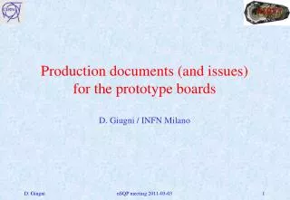
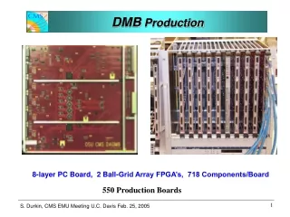
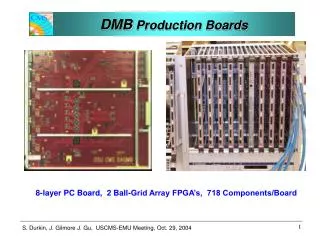
DMB Production Boards. 8-layer PC Board, 2 Ball-Grid Array FPGA’s, 718 Components/Board. DMB Production Boards. 220 boards delivered and tested 60 boards required repair 20 Dead Burr-Brown 16 bit ADCs 20 XiLinx eprom bit-errors Bad Chip Lots. Board are being boxed and stored

DMB Production Boards
E N D
Presentation Transcript
DMB Production Boards 8-layer PC Board, 2 Ball-Grid Array FPGA’s, 718 Components/Board
DMB Production Boards • 220 boards delivered and tested • 60 boards required repair • 20 Dead Burr-Brown 16 bit ADCs • 20 XiLinx eprom bit-errors • Bad Chip Lots Board are being boxed and stored until needed at Ohio State
DDU2004 Prototype DMB Input FPGAs 2 XILINX Virtex2Pro-20 4 Input FIFOs 512 KB each GBE FIFO 1024 KB VME FPGA XILINX Virtex2-500 9U VME board, 220 mm depth FMM output port SLINK Mezzanine board connector 15 Optical fiber inputs (just 1 for now) Gbit Ethernet Output To Local DAQ DDU Control FPGA XILINX Virtex2Pro-7
FPGA FPGA FPGA FPGA FIFO FIFO DDU 2004 Design FMM/Slow Control • BUSY • READY • L1 Throttle • Data Errors • Loss of Synch VME Slow-control and JTAG MGT-HSC DCC/DAQ Fiber links from 15 DMBs Multi-Gigabit Transmission via High-Speed Connector to backplane TTC control via backplane S-Link (for SP use) Transceivers Gigabit Ethernet To Local DAQ
DDU Performance • Beamtest results • Multiple DMB readout to DAQ • Good performance via DCC/S-Link and gigabit Ethernet spy path • Error-free operation at high rates • Passed all tests up to 6-times LHC expected data rate • DDU buffer size is more than sufficient for LHC • Status/error monitoring • All checks performed as expected, verified in offline software • Verified consistent fast monitoring path performance • Detected event and bunch counter inconsistencies • Caused by non-uniform implementation of EMU board resets • Conclusions • The DDU passed all tests with no problems • Ready for ESR
DCC Status: DCC Beam Tests • Fully stuffed DCC was used for Sept/Oct. CERN Beam test • It corrected several mistakes (clock driver from LVDS to PECL, Bus_LVDS buffers) in rev1. This board works • It distributes the TTC control signals. The L1A number and BX number sync with DDU in the FED crate, and sync with DMBs in the peripheral crates. • It reads data from DDU and sends data through SLINK to computer. With the ‘FakeDDU’, in addition to DDU, the DCC sends data at >240MB/s to the computer, which jammed the SLINK receiver. VME SLINK S_FIFO In_fpga spy in_fifo TTCrx M_fpga DDU C_bus
DCC Status: Some issues • Issues with the board: • On the DDR fifo, there are internal cross talk from D22 to D21 line. Get around: do not use D21, we only need 33 bits out of 40bits on the FIFO. • The DDR fifo works at 125MHz reading speed, but the manufacture downgraded its rating to 100MHz. Solution: Even 100MHz (800MB/s) is good enough for our application (Slink ~200MB/s) • At the CERN beam test, we do not have a readout system fast enough to handle the 200MB/s data, required by SLINK, this is not a real problem.
DDU /DCC Conclusion DDU/DCC/Controller ESR November 12, 2004 CMS Electronics Week Production will begin after passing Review