Download

1 / 24
240 likes | 322 Views
Vertex Detector: Engineering Issues. Craig Buttar University of Glasgow Cambridge GLDC meeting Sept 07. Design Features. Outer radius ~ 6 cm Barrel length ~ 14 cm Ladder widths 1-2 cm Disks to cover forward region. (GLD). (LDC). A bit larger than this. (SID).

E N D
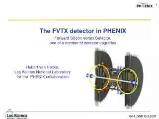
Vertex Detector: Engineering Issues Craig Buttar University of Glasgow Cambridge GLDC meeting Sept 07
Design Features • Outer radius ~ 6 cm • Barrel length ~ 14 cm • Ladder widths 1-2 cm • Disks to cover forward region (GLD) (LDC) A bit larger than this (SID)
Optimizing Vertex Performance • Close to IP • Reduce extrapolation error • Inner radius ~1.5cm • Position resolution (<5 microns) • Impact parameter resolution≤ 5µm 10µm/(p sin3/2 ) • Minimise multiple scattering • Material ~ 0.1X0/layer • 5 m resolution or better is possible with current sensor technology • Need good alignment to exploit this • Minimal mass is crucial • Constraints on mechanics • Constraints on power • Cooling • Power delivery • Alignment ILC target • Parametric simulation assuming: • 0.1% RL per layer • 5 micron resolution • 1.4 cm inner radius • Varying each parameter
Material budget ATLAS Tracker cosq=0.95 cosq=0.95 • Service handling at ends of barrel are the problem • The boring stuff is important! • Breakdown for pixels
Mechanical Support • 0.1% X0/layer 100mm of Si • Need to start with thin Si, typically 20mm • Thin supports • Carbon fiber-based supports, similar to D0 layer 0/CDF Layer00 • Foam-based (SiC, RVC) supports (LCFI) • Silicon picture frame (MPI) • System Issues • Planarity of the sensors • Bonding to thin silicon • Thermal bowing • Connection to external cables (University of Washington) (LCFI) MPI Design (SID inside support cylinder)
SiC Foam Ladder • 20 um thick silicon • 1.5 mm thick SiC foam • 8% relative density • Silicone adhesive pads • 1mm diameter 200 microns high on ~5mm pitch • ~0.14% X0 um mm SiC ladder um glue ladder block annulus block mm LCFI
RVC Foam/Silicon Sandwich Ladder • 20 micron thick silicon • 1.5 mm thick RVC foam • 3% relative density • Silicone adhesive pads • on ~5mm pitch • Tension ~1.5 N • ~0.08% X0 um mm um RVC sandwiched ladder Tension glue silicon spacer ladder block annulus block mm LCFI
Air Cooling • Air cooling is crucial to keep mass to a minimum • Require laminar flow through available apertures • This sets total mass flow – other quantities follow • Implies a limit on power dissipation • For SiD design • Use the outer support CF cylinder as manifold (15mm Dr) • Maintain laminar flow (Remax = 1800). • Total disk (30W) + barrel (20W) power = 50W average • For SiD ~ 131 µW/mm2. • Max T ~ 8 deg (Cooper, SID)
Cooling Studies Test model of 1/4 Barrel • Cold nitrogen cooling • Heaters at ladder ends • Parallel CFD simulations Power Extracted (W) • Flow 5-20 SLM • 0.52 g/s whole detector • Laminar flow LCFI Temperature Difference (K)
Alignment is critical • ILC physics programme depends on identification of secondary vertices • Ability to do this depends on tracking resolution • Tracking resolution dependent on alignment precision • Individual hit resolution may be O(5) m • Alignment must be better, so that contribution in quadrature does not degrade hit resolution
Alignment – LHCb VELO Hardware Design Metrology Software Measurement machine Individual modules during assembly Complete system 10m alignment BEFORE / AFTER Rigidity low CTE overlaps 10m alignment Alignment at few m level Iterative / non -iterative methods For ILC vertex detector Position of detectors on ladders to ~10mm Thin detectors Warping (SLD) Thin ladders not rigid Low mass beam pipe Vertex detector will move wrt experiment
Design • Design into system features for alignment • Rigidity, thermal and humidity expansion • This is difficult at low mass • Overlaps – not just for coverage, e.g. • VELO left, right half overlap • SLD CCDs
Metrology - importance • Starting point for alignment parameters • Constrains degrees of freedom not accessible from alignment system • e.g. large systematic on particle lifetimes is radius of barrel e.g. +/- 40 um on 4cm = 1% • e.g. aspect ratio of vertex detector gives systematic – important for FB asymmetries • Define/understand elements: • Ladders • Ideally rigid, 6 dof/ladder (372 for LCFI barrel) • Ladders are not a rigid object eg detector bow, CTE • Develop models? Difficult to measure during construction need to understand effect of thermal changes eg CTE, tension due to mechanics and services? (CTE studies by LCFI) • Greater no. of degrees of freedom than ladders x 6 (ATLAS has 34,992 dof) • Requires good initial survey and understanding of changes • Difficult to do under in-situ conditions
Power delivery • High currents to drive CCD clock pulses • Minimise voltage drop on power cables • Low resistance more conductor mass (Cu) • 0.5V drop at 6cm ~ 0.5%X0 • Use serial powering • Power at higher voltage, locally regulate at detector • Reduces conductor mass • 0.5V drop at 6cm ~ 0.04Xo • Issues • Failure in string • Coherent noise • Increase complexity of interconnects • UK-ATLAS activity for sLHC upgrade
UK Experience • ATLAS barrel and endcap silicon tracker, LHCb VELO • Sensors (strips) • Readout electronics • Module construction • Engineering • Cooling – liquid based • Alignment • LCFI • SLD CCD based vertex detector • ALEPH, DELPHI, OPAL strip-based vertex detectors • CDF Layer-00 strip-based vertex detector
Summary/conclusions • Low mass critical to achieve required IP • Challenging eg ATLAS is ~ 10.7%X0 for 3 pixel layers • Dominated by support and cooling • Target layer thickness 0.1%X0 (100mm Si) • Thin sensors • New support materials • Air cooling limits power to ~O(10W) • Also implications for services serial powering • Need to consider alignment in hardware • Design: overlaps in system (increase material) • Metrology during assembly • Warping of thin detectors and ladders • Report of LHC alignment workshop: CERN yellow report 2007-004 • Thanks to: Mark Thomson, Tim Greenshaw, Joel Goldstein, Chris Parkes, Val O’Shea, Richard Bates
Barrel Layout Beryllium support shell Foam cryostat Beam pipe Ladder (detector element) Fixed end Sliding end Spring Annulus block Substrate Annulus and ladder blocks Ladder block Beryllium support shell Silicon sensor Readout and drive chips
Barrel Layout • Looking at: • the radius of the layers • width of elements • tilt angle
Metrology - Equipment • Smartscope • Small scale items – not full system • High precision O(2) m XY O(10) m Z • Optical head • Automatic pattern recognition • Excellent for measuring sensor curvature • Individual sensors not double sided modules – no alignment to reverse side
Residualsare function of the detector resolution and the misalignments The geometry we are looking for is the one which minimizes the tracks residuals … to that Software Alignment Alignment principle : From this… Each individual ‘unit’ has six degrees of freedom Need to apply global transformation constraints
Misaligned detector Geometry not corrected Misaligned detector Geometry not corrected Fit the tracks Fit the tracks & the residuals Modify the geometry NO Plot and fit the residuals distributions NO Outliers rejected ? Non-linearities corrected ? Best mean and s values ? YES YES Detector aligned Detector aligned ITERATIVE NON-ITERATIVE Iterative / Not Iterative • All software alignment procedures follow one of these two forms: Iterative: fit biased tracks then fit alignment constants, iterate to reduce bias Non-Iterative: fit tracks and alignment constants simultaneously conclusion : both methods can be made to work well.
Global Alignment Method – H1, LHCb, ATLAS xclus =∑ai∙di+∑aj∙Dj Residuals expressed as function of misalignmentsDi Parameters di of the tracks (different for each track) xclus =∑ai∙di+ ex GLOBAL PART LOCAL PART ∂ c2 ∂ i ∂ c2 ∂ ∆i = = 0 • Establish linear expression of residuals • as a function of mis-alignments. • Fit the tracks simultaneously with the alignment constants xclus =xtrack + ex rclus = (xclus - x) Alignment minimise c2res = ∑ ∑wclus∙r2clus Get all track parameters and all misalignment constants simultaneously 1 single system to solve. But this system is huge ! (Ntracks∙Nlocal+Nglobal equations) BUT…
Matrix Inversion … … kCkglobal Hk kwkxk D = 0 0 … … … … kwkak 0 0 dk Cklocal HkT 0 0 … … … … The matrix to invert has a very special structure: Nglobal Nlocal xNtraces Inversion in section (implemented in the code MILLEPEDE V.Blobel -NIM. A 566), The problem becomes only Nglobal xNglobal IfNglobal 100 , the problem can be solved in seconds
Other Interesting Techniques • Kalman Filter Alignment – CMS • Iterative • Updates alignment constants immediately after each track • SLD • Residuals as a function of misalignments • Fit residuals as a function of position • Determine alignment constant from matrix inversion