System Coordination Library (SCL) Framework
The rise in popularity of FPGAs and other devices as accelerators reveals critical challenges in implementing effective coordination in massively parallel computing systems. This document proposes a System Coordination Library (SCL) that aims to standardize communication across heterogeneous devices. By providing a comprehensive framework for device communication and task mapping, the SCL facilitates the transition from formulation to design phases, enabling developers to leverage existing frameworks like MPI. The solution aims to enhance interoperability and portability of applications while addressing the long lifecycle of software compared to hardware.

System Coordination Library (SCL) Framework
E N D
Presentation Transcript
Vikas Aggarwal Rafael Garcia Abraham Sanchez Philips Shih System Coordination Library (SCL) Framework
Challenges & Problems FPGAs and other devices (eg. Cell & GPUs) gaining popularity as accelerators Lack of direct co-ordination amongst devices precludes usage as peers in massively parallel machines Development support for large-scale applications is lacking Device design languages for FPGAs are migrating towards true HLL Missing piece: System-level Coordination Library, extension to HLL Complete lack of inter-operability, several IDEs and devices gaining popularity in smaller domains Standardization of communication, compatibility amongst different devices is highly desirable to capture larger user-base Lack of transition from Formulation phase to Design phase 2
Proposed Solution Design a System Coordination Library to facilitate coordination amongst heterogeneous set of devices Provide a familiar coordination/communication interface to parallel program developers, employ MPI-like interfaces Standardize coordination primitives across different technologies Provide a higher level of abstraction for communication Allows applications to be more portable across changing platforms Life cycles of software are generally longer than the corresponding hardware version Provide communication based on relevant communication infrastructure Build communication from bottoms up, employing existing work and effort like MPI, GenAPI etc. Provide a transition from Formulation phase to Design phase Allow parallel programs to be expressed as task graphs Provide a framework to auto-generate communication infrastructure based on mapping of tasks to different devices 3
DARPA Study – Quick Glance Formulation -- strategic design abstraction Formulation – prediction, tradeoff analysis Design – system coordination language Design – device design languages Design -- library reuse (modules, cores) Translation Execution F VHDL Gedae etc. AccelDSP Carte C Impulse C • Device design languages for FPGA devices are migrating upward in abstraction towards true HLL • Missing piece in Design layer is System Coordination Library, extension to HLL … D FPGA devices (e.g. Stratix-II/III, Virtex-4/5) x86 Cell etc. T E
Bigger Picture Formulation enables abstract modeling of algorithms Allows decomposition of apps into constituent tasks Allows automated performance prediction for a particular algorithm decomposition Missing Components Multi-FPGA applications still present a major development bottleneck Automated grouping & mapping of tasks onto resources provide tremendous benefits Several techniques have reaped benefits of automated DSE in conventional computing Bridging Formulation and Design phases Providing automatically generated framework for communication between tasks Auto-generation of communication Infrastructure using the mapping information Suggested mapping of tasks on resources Corresponding task graph of application Example RCML model of a conceptual application 6
Basic Definitions H(f) Programming Model • SCL Task: Finest unit of computation in SCL • Task definition code: Implements the computational part of a task in a DDL • Task graph: Defines tasks graph, by describing the tasks and the communication between them • Mapping: Provides mapping of tasks onto devices H(f) FFT FFT IFFT IFFT Architectural Model • SCL Device: finest granularity of computational resource that can execute one or more task and has a unique address within a platform • SCL Platform/Node: a set of SCL compliant devices connected together by some underlying topology into a single uniquely addressable entity in the system • SCL System: a set of platforms connected together by some underlying topology • SCL Resource graph: maintains information about all devices and platforms in the system with their interconnection
Co-ordination Using SCL • Intra-device-level coordination: coordination between tasks within a single device • Two tasks mapped to a single FPGA or two SPEs of a single Cell • Intra-platform-level coordination : coordination between tasks on different devices on a single platform • Coordination between a Nallatech board and its host processor • System-level coordination - coordination between tasks mapped on different platforms • A Nallatech board communicating with a PS3 and a Gidel board SCL Compliance : to support coordination at above levels of hierarchy • A device is SCL compliant if • It can support communication between multiple tasks mapped onto the same device, • And provides some mechanism for specifying communication with the platform • A platform is SCL compliant if • It is composed of SCL compliant devices, • And can support communication between tasks running on different SCL-compliant devices within the platform, • And provides some mechanism for specifying communication external to the platform • A system is SCL compliant if • It is composed of SCL compliant platforms, • And can support communication between multiple SCL-compliant platforms
Communication using Hierarchy • Hierarchical addressing • Each platform has a unique “platform address” in the system • Each device has a unique “device address” in its platform and hence in the system • Use of address to build communication structure • SCL Resource graph • Contains knowledge of the SCL compliant resources available in the system in hierarchical manner • SCL parser will use info. from the graph to find appropriate communication routines • Communication constructs will be auto-stitched in the task definition code C P2 P1 P3 P4 P5 Platforms D1 System Devices Interconnect D1 D1 D1 D1 F C C C Given a task graph of the application and a resource graph for the system, a mapping of tasks onto devices is required to run the application D2 D2 D2 D2 D3 F GPU F Cell F
Quick Peek: Example Generate random numbers Process numbers edge1 A B Architecture Independent System-level Coordination Architecture dependent IDE Tasks to resource Mapping random.cpp tasks.map systemApp.scl SCL_Init( … ); for (unsigned i=0; i < 100; i++) { int x = rand(); scl_send( "out1", &x, … ); } Num Micro-tasks : 2 ... ---------- Task 1 : random Target: x86 IDE: C++ Address: Library: ... ----------- Task 2 : process Target: FPGA IDE: Handel- C Address: ... Edge edge1; Task random ( Out out1 ) { edge1 = out1; } Task process ( In in1 ) { in1 = edge1; } process.handelC SCL_Init( … ); int acc=0; for (unsigned i=0; i < 100; i++) { int temp; scl_receive( "in1", &temp, … ); acc += temp; } • Defines application as a task graph • Define communication between tasks as edges in the task graph process.impulseC
Compilation Process • Step1 : Parse task-graph in “.scl” file • Gather information about “communication edges” from .scl file • Definition for “SCL_” functions will be populated with one entry for each edge at a later stage • In future, could also provide a script to add partially auto-generated functionality for legacy code in existing languages • Step 2 : Reading “.map” file • Parser would extract the information from the .map file about the mappings of various tasks • Definition of “SCL_” functions is auto-generated based on this mapping information • Step 3: Build tasks in their native build environment • Definition for SCL functions is linked to the definition generated in previous step • Run-time service responsible for spawning tasks/(could be a manual process in the beginning)
Basic Co-ordination Primitives • Identify baseline functions to support basic communication in the initial phase • Identify necessary static and run-time parameters • Focus on synchronous blocking communication based on message passing(dominant mode of communication in MPI) • Consider other modes wherever applicable to facilitate efficient data transfer • Shared memory constructs for data movement within a platform • Streaming communication model – for systems capable of supporting this mode
Challenges • Mapping from tasks to device requires a static-compile time behavior • # of processes and communication is statically defined at compilation • Is it over restrictive? – majority of applications follow a well-behaved structure • Static task graphs are a well studied problem • Re-compilation required in most cases when mapping changes or number of tasks changes – explore ways to minimize such situations • Allow for changing the task graph by changing parameters in .scl file in acceptable cases • Provision of loops to accommodate variable number of tasks in the graph • System should allow for post-compile time scaling on homogeneous node
SCL Parser Requirements • Basic grammar to define SCL task graph language • SCL_FILE SCL_CONSTRUCT ARITH_OP EDGE_ASSIGNMENT EXPR EDGE_DECLARATION PORT_TYPE TASK_HEADERTASK EDGE_TYPE LOOP TASK_DEFINITIONLOOP_EXPR • Build abstract syntax tree and extract edge & task information • Generate platform-specific code that implements specified communication behavior
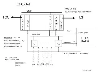
SCL Parser Design • SCL Parser readstask graph definition • Finds all tasks • Determines communication • SCL Code Generatorreads .map file • Determines resource mapping • Implements SCL callsin native platform code SCL_SEND(…) SCL_RECEIVE(…) …
Eclipse • Using Eclipse environment to develop the SCL parser • Compatible with other HPCSA tools • Allows easier integration with other tools/entry points • RCML, PTP • Portable across most operating systems • Windows, Linux, Mac OS X • Graphical editing environment • Easy plug-in based integration
Eclipse-based framework for developing Domain-Specific Languages (DSL) • DSL: small specialized languages used to raise the abstraction level of software • Removes extraneous programming details • Provides for simplified specification • Features • Allows specification of the grammar, creates a parser • Generates a complete Eclipse text editor • Syntax coloring, Syntax checking / Error markers • Code completion • Navigation, Folding • Outline, Find References
SCL Environment Outline view Text Editor Project Files Console
Graphviz • Converts textual descriptions of graphs into diagrams • Aids in design and verification of task graphs • Textual description is automatically derived from user’s design and converted into Graphviz language digraph edge_map { P1 -> C1 [ label = "E1" ]; P2 -> P1 [ label = "E2" ]; G1 -> P1 [ label = "E3" ]; }
Simple SCL example • Installation • Download self-extracting SCL plugin and extract into Eclipse plug-in directory • Project setup • Open Eclipse->File->New Project->Xtext DSL Wizards->SCL Project • Project specification • Describe SCL task graph in the model.scl file • Create and specify model.map file • Task graph parse & code generation • Run the .oaw file • Verification • View Graphviz diagram and verify proper task graph description • Compilation & Execution • Compile task definition code & execute application
Proof of Concept – Building First App • Initial emphasis: SCL coordinating computing on two different platforms selected from heterogeneous suite (FPGA, CPU, GPU, etc.) • Feature FPGA as superior device technology • Multi-FPGA platform – Gidel board with a host CPU • Development environments • Impulse C, VHDL – for FPGA • C++ – for processors • Multi-FPGA platform • Applications • Target tracking application using multi-fpga design
Target tracking – Task Graph C1 C1 CF1 CF2 F1 F1 F3 F2 F4 BE1 E1 F3 F2 F4 E3 E2 F2/F3 edge E2, E3 ; taskId t[2] ; loop(i=2; i<=3; i++) ( t[$i] = $i ; task F$i( output out1, input in1, input in2) { in1 = BE1 ; in2 = E$i ; E$(i-1) = out1 ; } } F1 C1 edge E1 ; bedge BE1 ; task F1 ( output out1, output out2, input in1, intput in2) { in1 = CF1 ; in2 = E1 ; CF2 = out1 ; BE1 = out2 ; } edge CF1, CF2 ; task C1 ( output out1, input in1 ) { in1 = CF2 ; CF1 = out1 ; }