P-REV Initial PCB
This document outlines key design considerations for microcontroller peripheral usage, focusing on input and output interfacing. It details the integration of multiple peripherals, including ATD, UART, USB, and PWM for effective motor control and data transmission. Key algorithms for data handling, traction control, and calibration processes are discussed along with interrupt-driven mechanisms for sensor data collection. Flow charts illustrate system architecture and functionality, facilitating a deeper understanding of the microcontroller's design and operational efficiency.


P-REV Initial PCB
E N D
Presentation Transcript
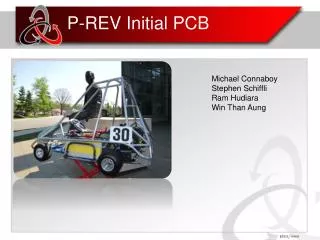
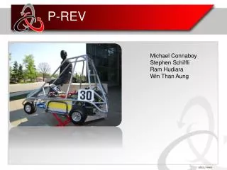
P-REV Initial PCB Michael Connaboy Stephen Schiffli Ram Hudiara Win Than Aung
Design Considerations(I) • Microcontroller Peripheral Usage • Input Interfacing • 9 ATD • 3 UART (1 for GPS,2 for left/right motor controller) • Output Interfacing • 1 USB (micro to atom board) • 2 PWM (motor controller output adjustment) • 1 UART (Xbee wireless module) • Atom Peripheral Usage • 1 USB to MIMO touch screen • 1 USB to microcontroller
Design Considerations(II) • Microcontroller Code • Polling loop + interrupt-driven • Using vectored interrupts for all digital inputs • Using a polling loop to grab all analog sensors’ data • Atom Code/Basestation • Polling loop
Flow Chart – Main Loop • The main iterative loop • Average buffered analog data • Retrieve the GPS data and steering angle data (interrupt driven) • Calculates power ratio • Power distribution ratio to the rear wheels based off of the steering angle and the geometry of the car • Transmit the data
Flow Chart - Sensor Gathering • Sensor gathering routine • Interrupt driven by a timer • Captures analog sensor values and stores them into a circular buffer • Sets a flag if the buffers are full
Flow Chart - Traction Control • Traction Control algorithm • Looks for an RPM sensor update • RPM sensor reports a time stamp every 8 pulses • Calculates the RPM • Finds difference between desired power ratio and actual power ratio • Calculates appropriate adjustment • Scales adjustment based on throttle position • Updates the motor controller
Flow Chart - Calibration • Receives data from the atom via USB • This includes calibration data for throttle and break position, steering angle, and kart geometry
Current Status • Done • GPS • UART • Xbee • Winapplication GUI • In Progress • Researching USB communication ( bidirectional microcontroller & atom) • Main loop • Traction Control
Q&A • Questions?