Download
1 / 14
140 likes | 275 Views
HIE-ISOLDE (High Intensity and Energy) project Protection of superconducting solenoids. MPE work shop – December 14, 2010 G.J. Coelingh TE-MPE-CP. Overview. HIE-ISOLDE Project Overview, layout, work structure, QPS budget Circuits to protect Quench Detection Magnet, Current Leads

E N D
HIE-ISOLDE (High Intensity and Energy) project Protection of superconducting solenoids MPE work shop – December 14, 2010 G.J. Coelingh TE-MPE-CP
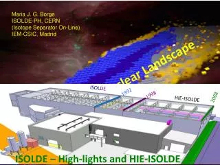
Overview • HIE-ISOLDE Project • Overview, layout, work structure, QPS budget • Circuits to protect • Quench Detection • Magnet, Current Leads • Energy Extraction • Resources • MPE work shop – December 14, 2010 G.J. Coelingh TE-MPE-CP Y. Kadi HIE-ISOLDE Proposal, IEFC, August 21, 2009
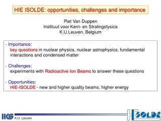
Scope of HIE-ISOLDE Energy Upgrade: The HIE-ISOLDE project concentrates on the construction of the SC LINAC and associated infrastructure in order to upgrade the energy of the post-accelerated radioactive ion beams to 5.5 MeV/u in 2013 and 10 MeV/u by 2014/2015 Intensity Upgrade: The design study for the intensity upgrade, also part of HIE-ISOLDE, starts in 2011, and addresses the technical feasibility and cost estimate for operating the facility at 10 kW once LINAC4 and PS Booster are online. The 30 kW option (SPL beam) will be studied at a later stage
Steering Committee International Advisory Panel 1.1 Project Leader – Y. Kadi (EN/HDO) 1.2 Project Safety Coordinator – A.P. Bernardes 1.3 Technical Coordinator – M. Pasini BE/RF HIE-ISOLDE Project 1. Project Management 1.4 Design Study Coordinator–R.CatherallEN/STI 1.5 Budget and Planning – E.Delachenal EN/GMS HIE-LINAC 2. Linac Systems 2.1 Cavity RF BE/RF 1.6 Administration – E. Cochet EN/GMS 2.2 Cavity Design manufacturing EN/MME TE/VSC 2.3 Beam dynamics BE/RF-ABP 2.4 Cryomodules TE/MSC EN/MME 2.5 Beam Instrumentations BE/BI 2.6 SC Solenoid TE/MSC 2.7 Beam transfer line (magnets) TE/MSC 8.1 Safety Coordinator GS/DI 8. Safety 2.8Linac Integration EN/MEF 8.2 Radioprotection DG/SCR 2.9 Vacuum TE/VCS 8.3 Access System GS/ASE 2.10 Survey BE/ABP 8.4 Access System GS/ASE 3.1 Civil Engineering GS/SEM 3. Infrastructure & Integration Work Breakdown Structure 3.2 Integration EN/MEF 3.3 Cooling ventilation EN/CV 3.4 Electrical systems EN/EL 3.5 Cryogenic system TE/CRG 3.6 Power converters TE/EPC 3.7 Industrial Control systemEN/ICE 3.8 Beam Control system BE/CO 3.9 Interlocks TE/MPE 4.1 Single cavity test BE/RF 4. Installation & Commissioning 4.2 Cryomodule test BE/RF 4.3 Transport & Handling EN/HE 4.4 Planning & Installation EN/MEF 4.5 Linac commissioning BE/RF-OP Design Study 5. Target Study 5.1 Target design EN/STI-HE 5.2 Front Ends EN/STI TE/EPC-ABT 5.3 Beam Diagnostics BE/BI 7. Injection & Beam distribution 7.1 Off line separator EN/STI 6.1 Layout upgrade EN/MEF 6. Target Area and Class-A Lab Integration 7.2 Separator areas EN/STI 6.2 Cooling and ventilation EN/CV 7.3 Experiment Hall EN/MEF 6.3 Electrical systems EN/EL 7.4 Beam lines BE/ABP 6.4 Vacuum TE/VCS 6.5 Survey BE/ABP 6.6 Civil engineering GS/SEM 6.7 LL Control system EN/STI
HIE-ISOLDE material budget • MPE work shop – December 14, 2010 G.J. Coelingh TE-MPE-CP
HIE-ISOLDE Schedule • Important milestones for Energy Upgrade: • Start project Jan 1st 2010 • Start construction by Jun 2010 • Launch Procurement of Cryogenics equipment: • Market survey by Mar 2010 • Tech. Specific. By May 2010 • Finance Committee by Sep. 2010 • Cryogenics installed and commissioned Jun 2013 • High energy beam line (5.5 MeV/u) installed by Oct 2013 • 10 MeV/uLinac installed by 2014/2015 • Commissioning organized inline with L4 and PSB commissioning April 2010 planning - to be updated Cold test of first cryo-module in April 2013 • MPE work shop – December 14, 2010 G.J. Coelingh TE-MPE-CP
Circuits • 8 individually powered circuits with S.C. solenoids of 130 mH each • Nominal current 450 A – Stored Energy 13 kJ • Powering scheme tbd. Grounding, Series/parallel extraction • Protection delay tbd. This will determine EM or SSt switch • MPE work shop – December 14, 2010 G.J. Coelingh TE-MPE-CP Y. Kadi HIE-ISOLDE Proposal, IEFC, August 21, 2009
Quench Detection • Magnet Detection based on existing digital LHC – SAM detectors • 4 redundant voltage taps on layer 0, layer 8, layer 12 and layer 20. • First tap on the top and the redundant at the bottom. • The difference will be 0.5 turns which should be negligible for the detection system • MPE work shop – December 14, 2010 G.J. Coelingh TE-MPE-CP Y. Kadi HIE-ISOLDE Proposal, IEFC, August 21, 2009
Quench Detection & Controls • Lead detection depending on lead type but most likely conventional cupper model will be used. Tbd. • Controls/Data transfer to be determined – Field Bus or Ethernet? • Valid for Detection and Extraction • Interlocks – PC-QPS-EE-PIC. Tbd. • MPE work shop – December 14, 2010 G.J. Coelingh TE-MPE-CP Y. Kadi HIE-ISOLDE Proposal, IEFC, August 21, 2009
Strategic Plan for EE • Solid State Switch development recently started • Goal: Prototype by May/June 2011 • Challenge to finish series production before 2.5 years from now • In parallel: upgrade existing LHC 600 A EE system; improvements from exploitation/maintenance points of view • 10 systems can be delivered within 2 years • If choice will be Solid State - use EM systems as spares for LHC • MPE work shop – December 14, 2010 G.J. Coelingh TE-MPE-CP Y. Kadi HIE-ISOLDE Proposal, IEFC, August 21, 2009
EE: Solid State or EM • Solid State Switch: Semi-conductor IGCT • Integrated Gate Commutated Thyristor Fast and “maintenance” free vs Forward Losses – water cooling • Electro-Magnetic circuit breaker very lowforward losses vs maintenance (preventive & corrective) IGCT and its integrated drive electronics. Two, 600A extraction systems in a common rack • MPE work shop – December 14, 2010 G.J. Coelingh TE-MPE-CP Y. Kadi HIE-ISOLDE Proposal, IEFC, August 21, 2009
Resources 2011 - 2012 • Project Manager: 20% - 2011 15% - 2012 • Project Engineer EE: 20% - 2011 20% - 2012 • Project Engineer QPS: 25% - 6 months 2011 10% later • Technician: 20% - 2011 10% - 2012 • Design: 35-50% - 6 months 2011 10% later • MPE work shop – December 14, 2010 G.J. Coelingh TE-MPE-CP Y. Kadi HIE-ISOLDE Proposal, IEFC, August 21, 2009
Thank you for your attention MPE work shop – December 14, 2010 G.J. Coelingh TE-MPE-CP