Download
1 / 38
400 likes | 571 Views
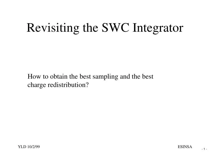
Revisiting the SWC Integrator. How to obtain the best sampling and the best charge redistribution?. C 2. 1. 2. C 1. 1. 2. Revisiting the SWC Integrator. Sampling during 1 Redistribution during 2. . C. Vi. . Perfect Sampling. Input: (Vi - 0) Output: Q

E N D
Revisiting the SWC Integrator How to obtain the best sampling and the best charge redistribution? ESINSA
C2 1 2 C1 1 2 Revisiting the SWC Integrator Sampling during 1 Redistribution during 2 ESINSA
C Vi Perfect Sampling Input: (Vi - 0) Output: Q Theoretically: Q = C * (Vo - 0) Vo = Vi Vo ESINSA
C Vi V2 V1 V1 V2 To be sampled Effectively sampled Resistive Switches! Switches are resistive. Resistance of a switch is non linear. ESINSA
Q Vi 0 Non Linear Capacitances! C Vi ESINSA
V2 V1 Metal 1 Polysilicon 2 Polysilicon 1 Si Substrate Non Linear Capacitances Electric field in polysiliconforms depletion layers increasing the effectivedistance between the capacitor plates. Depletion layer is thinnerif doping is higher.Depletion layer is thicker if electric field is higher. 2 1 Oxide thickness Effective separation = function( V2-V1, …) ESINSA
Clock Feedthrough C Vi V2 V1 V1 V2 To be sampled Effectively sampled Clock Feedthrough! ESINSA
Cp hi Vi Vj lo Clock Feedthrough We will assume here that the transistor has no internal resistance. ESINSA
hi Cp ON Vi Vj th OFF Vt hi lo th (Memelinck Diagram) Vj = Vi lo Clock Feedthrough ON th = Vi + Vt if Vi < ( hi - Vt ) th = hi otherwise ESINSA
hi Cp ON Vi Vj th C OFF hi lo th Vj Vi Clock feedthrough lo Clock Feedthrough OFF DV = (th - lo) * Cp / (C + Cp) Vj = Vi - DV ESINSA
Vi Vj C Charge Injection! ON i j channel ON OFF Charge injection ESINSA
Charge Injection • Charge injection depends on a lot of parametersand is very non linear: • MOSFET • Clock • Input Source • Capacitor • Parasitics • Signal ESINSA
Charge Trapping! ON j i ON OFF Charge trapping j i OFF j i Charge release ESINSA
Sources of noise Source of noise Vi C Source of noise Source of noise Noise Feedthrough! (and noise aliasing brings a lot of fun) ESINSA
C2 2 C1 2 Vout Perfect Redistribution Theoretically: DQ2 = Q1 Vout= - C2 * Q2 ESINSA
Opamp Limitations! • Add to the list of issues described above • Opamp Performances • Gain • Offset • Bandwidth • Slew Rate • Noise • Distortion • Settling Time • and other weird things.. ESINSA
A few Solutions ESINSA
Solutions (a) The most dangerous problems are related to theCharge Injection. This is a strongly Non Linear effect. Fairly Unpredictable. Charge Injection must be eliminated. ESINSA
1d C1 Vi 1 a b 1d 1 c delay t0 t1 t2 Solutions (a) At each t1: Same input source connected, Vb always at 0, charge injection in C1 is (unknown!) constant. ESINSA
1d C1 Vi 1 a b Cp 1d 1 c delay t0 t1 t2 Solutions (a) At each t2: b is floating (if Cp negligible), No charge injection in C1. ESINSA
2 t4 t3 Solutions (a) C2 2 d b Virtual ground At each t4: b at 0. Everything being constant, Charge injection in C2 is (unknown!) constant. ESINSA
Solutions (a) Using delayed clocks, charge injection is constant. If Cp is negligible, the charge injection creates a DC offset. Otherwise, charge injection is attenuated by ratio Cp/C. ESINSA
C2 C1 1d 2 Cp 1 2 Solutions (a) In fact, charge injection is attenuated by the ratio Cp/C1. This capacitor must be minimized. ESINSA
Cp’’ Solutions (b) Clock feedthrough can be at least partially compensated usingCMOS switches: Cp’ Vi Vj C t0 t1 ESINSA
Solutions (b) The CMOS switches are also less resistive and allow to switch a signal with a rail to rail dynamic range. Still their resistances are very non linear. Vi Vj C t0 t1 ESINSA
C1 C2 C1a C2a 1d 2 1d 2 1 2 1 2 CM CM 2 1 2 1d C1b C2b Solutions (c) Symmetrical differential architecture brings a lot of solutions! ESINSA
C1a C2a axial symmetry C1b C2b noise Solutions (c) A lot of perturbations are applied as a common mode signal and is rejected by the high CMRR of the structure. ESINSA
C1a C2a axial symmetry C1b C2b Solutions (c) Symmetrical differential architecture requires a lot of expertise. It is essential to master all the matching techniques! No mistake !!! ESINSA
R R Vi Vi C/2 C R -Vi Vi C Vi C 2 R R -Vi C Solutions (c) Single ended filter structure has to be mapped in a symmetrical differential structure. A few examples: ? ? ESINSA
Cost Power Symmetry Noise Distortion R R R R R R Solutions (c) Other mappings: ESINSA
Solutions (d) There is an incredible collection of other issues and solutions. ESINSA
Wrapping-up... ESINSA
C C Va Vb Vc C C Wrapping-up... 1d 2 1d C 2 1 1 C Va being a staircase waveform, how are Vb and Vc? ESINSA
sampling redistribution +1.0 -1.0 -1.0 2 1,1d 2 1 ,1d 2 1 ,1d Applying a Staircase 3 2 Va 1 0 -1 -2 0.0ms 0.2ms 0.4ms 0.6ms 0.8ms 1.0ms 1.2ms current time ESINSA
2 1,1d 2 1 ,1d 2 1 ,1d Ideal Waveforms 3 Vc 2 Va 1 Vb 0 -1 -2 0.0ms 0.2ms 0.4ms 0.6ms 0.8ms 1.0ms 1.2ms current time ESINSA
3 Vc 2 Va 1 Vb 0 -1 2 1 ,1d 2 1 ,1d 2 1 ,1d -2 0.0ms 0.2ms 0.4ms 0.6ms 0.8ms 1.0ms 1.2ms current time Real Waveforms ESINSA
2 1 ,1d 2 1 ,1d 2 1 ,1d Ideal and Real Waveforms 3 Vc 2 1 0 -1 -2 0.0ms 0.2ms 0.4ms 0.6ms 0.8ms 1.0ms 1.2ms current time ESINSA
SWC Integrator Hard to believe? Symmetrical Differential SWC integrators have such qualities that it is possible to use them to build fully integrated ADC exceeding the performances of CD audio, without calibration. Some care is nevertheless needed . ESINSA