Download
1 / 22
220 likes | 393 Views
Tweety Operation Manual. Tweety Operation Manual. Refurbish History. Motor. 1) Cummings Diesel (V6), 1984 2) Red Line 3000 (hums at 2800) 3) Top Speed 60 MPH. Oil. 1) Shell Retilla Diesel Oil 2) Dip stick, normal location, screw dipstick type. Rear Differential.

E N D
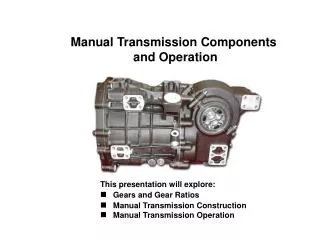
Motor 1) Cummings Diesel (V6), 1984 2) Red Line 3000 (hums at 2800) 3) Top Speed 60 MPH
Oil 1) Shell Retilla Diesel Oil 2) Dip stick, normal location, screw dipstick type
Rear Differential 1) Still is a 1951, and was originally designed for V12 dual Carb gasoline motor
Body 1) Original Body was 1951 LaFrance 2) Refirb by SuperVac: Changed Open cab to four person enclosed for rollover protection Cab windows are necessary for cab integrity Both rear boxes added to include storage spaces (six compartments, and rear compartments) Running boards changed to aluminum for less weight
Chassis 1) left as original chassis by SuperVac
Booster and B-Foam tank Booster and Foam tank are one plastic tank with two cells: United Plastics Tank, CA. company. 1) 300 gallons water 2) 220 (Class B) gallons foam: 3M 3/6% ATC; 10 -15 years old, but has been sealed
A - Foam Tank 1) A-Foam 55 gallons, sits below the proportioner, and is portable, proportions not educts. 2) Operation of A-Foam system: 1) Attack line pulled and flowing Start motor 2) Three position switch, adjacent to percentage valve, (flush, prime, run) turn to prime, squeeze bulb to prime 3) Percentage valve selects: 0 -1% (check to verify) Run up motor to full throttle 4) Make sure quarter turn valve (orange handle) is open 5) After foam is in the pick-up tube, turn the three position valve to "run" 6) Flow the line 7) When finished: a) close pick-up tube b) turn indicator to flush c) flow until clear 3) Leaks may occur at the pick-up tube; crack in pick-up tube (check fill tower for cracks)
B-Foam Operation 1) The B-Foam system is an eductor 2) The manufacturer is from Williams Fire Control (bought as a package); package designed to deliver 1000 gallons per minute at 3% 3) The nozzle is a self-educting nozzle: 1000 gpm nozzle; can use white/clear hose and drop into 55 gallon drum for more foam delivery 4) B-foam drain is above differential housing: quarter turn valve (verify) Operation of system: a) Establish water supply b) Put engine in pump c) Quarter turn (blue) valve at base of master stream supplies water for master stream d) Open (green) quarter turn valve at base of master stream
Pump Operation 1) Arrive on scene 2) Set microbrake 3) Clutch engaged 4) Pull PTO (on dash above shifter, silver t-handle), is quarter turn handle; turn counter clockwise and pull, then turn quarter turn clockwise until firm 5) Bring pump transmission to third gear 6) Release clutch, slowly 7) listen to pump engage and watch speedometer reading bounce 8) Set pump lock levers for third gear 9) Dismount and pull tank to pump, engage cooling 10) Tank pump and tank fill are same valve lever on pump panel
Pump Operation 8) Set pump lock levers for third gear 9) Dismount and pull tank to pump, engage cooling 10) Tank pump and tank fill are same valve lever on pump panel
Foam 1) A-Foam is 55 gallons 2) B-Foam is 220 Gallons
Water 1) 300 Gallon Poly tank
Specifications 1) Diesel: 40 gallon tank (verify)
Basic Starting and Operation 1) Turn key 1/4 to on 2) Depress clutch 3) Hit either start button (recommended to hit both start buttons) 4) Microbrake Very hard to depress brake peddle enough to release hydraulic brakes Can turn off switch, then depress brake peddle. The brakes are hydraulic Reservoir for brakes is under Officer's seat 5) Shifting: Non-syncromesh four-speed Shifting pattern is not normal, third gear is up and is pump gear Reverse is tricky because of the levers that lock into pump. The upper keeps you from third and reverse: leave down so you don't end up in reverse by accident The lower lever keeps it in third gear when pumping
Pump Panel Pump Panel from top left to bottom right: This panel was modified by SuperVac 1) Tank and foam level lights; panel heater light that indicates heat tape is activated 2) 2 1/2" discharge gauges across top 3) Pump overheat light (if pump is overheating this light will illuminate) 4) Below gauges are the 2 1/2" drains 5) Left side 2 1/2" discharge valves 6) Preconnect valve R-side which is plumbed for A-foam 7) Preconnect valve L-side is not foam, straight water 8) Valve for R-side 2 1/2" discharge 9) Tank to pump 10) Top valve 2 1/2" intake suction 11) Same 2 1/2" suction on L - side 12) Compound and pressure gauges; tach, temp, oil pressure 13) Prime is below gauge cluster; reservoir is under wood deck behind tank lights 14) Throttle below gauge cluster Trouble shooting: If pump wont prime the PTO cable probably isn't pulled and quarter turn set. Repeat pump engage sequence.
Emergency Lighting 1) Main dash: Quarter turn master switch, this must be on for any electrical to be used This has to be on for any lights to work Radio power Fan defogger All accessories 2) On dash is six position toggle for: Emergency lights and spots 3) The VHF and UHF radios are behind seats UHF is computer programmed VHF is MT500 radio convert-a-com