Internet
Internet. MIS 416 – Module II Spring 2002 Networking and Computer Security. Topics. What is Internet? Internet Protocols Protocol hierarchies The OSI reference model Services in the OSI model. What is the Internet?. It is a network of networks Any network connected to the internet

Internet
E N D
Presentation Transcript
Internet MIS 416 – Module II Spring 2002 Networking and Computer Security
Topics • What is Internet? • Internet Protocols • Protocol hierarchies • The OSI reference model • Services in the OSI model
What is the Internet? • It is a network of networks • Any network connected to the internet • Conform to certain naming conventions • Must run the IP protocol • IP protocol is also called Internet dial tone • Internet has a hierarchical topology • End Systems connected to local ISPs through access networks • Access Network examples – LAN, telephone line with a modem, high speed cable networks • Local ISPs connected to regional ISPs, regional ISPs connected to national & international ISPs • Construction analogous with Lego construction
Role of Internet • Allows distributed applications to exchange data with each other • Applications include: FTP, Telnet, Mail, WWW, distributed games, video conferencing • Provides two kinds of services • Connection Oriented Service (TCP): Establish connection prior to data exchange, coupled with reliable data transfer, flow control, congestion control etc. • Connectionless Service (UDP): No handshake prior to data exchange, No acknowledgement of data received, no flow/congestion control
Modem Home Ethernet University Internet – Information Flow Multi-media ISP Security Lan ISP Hosting Platform Origins of Online Content
Protocol Hierarchies • Internet is a very complex system • Set of layers and protocols represents the Network Architecture. • Protocols are stacked vertically as series of ‘layers’. • Each layer has a well defined interface. • Allows for easy replacement of layer • Each layer offers Services to layer above, shielding implementation details. • Each layer on one machine communicates with corresponding layer on another machine using Protocol for the Layer.
Layers, Protocols & Interfaces Layer n/n+1 interface Layer n/n+1 interface Layer n protocol Layer n Layer n Layer n-1/n interface Layer n-1/n interface Layer 2/3 interface Layer 2/3 interface Layer 2 protocol Layer 2 Layer 2 Layer 1/2 interface Layer 1/2 interface Layer 1 protocol Layer 1 Layer 1 Physical communications medium
Protocols A protocol defines the format and the order of messages exchanged between two of more communicating entities as well as the actions taken on the transmission and/or receipt of a message or other event. Hi TCP Connection Request Hi TCP Connection Response Got the Time? Get http://www.ibm.com/index.html 8:50 Index.html
Internet Architecture – Simple Analogy • Examine the mail system in context of layering and standardized protocols • Each letter has a standard format for the address. Sender’s Home Receiver’s Home Sender’s Mail Box Receiver’s Mail Box Sender’s Post Office Receiver’s Post Office Routed
Layered Architecture - Internet Host A Host B Examples Message Http, Ftp, Smtp, Telnet Application Layer Application Layer Packet (Bridge) Transport Layer Transport Layer TCP, UDP Port-to-Port Datagram (Router) Network Layer Network Layer IP Host-to-Host Frame (Hub) Link Layer Link Layer Ethernet, FDDI Node-to-Node Physical Network
Application Layer • Implements application protocol • Users invoke applications using this protocol • Application Layer Protocol defines • Types of messages exchanged e.g. request or response • Syntax of the various message types, such as, fields in the messages and how they are delineated • Semantics of the fields i.e. meaning of information in each field • Rules for determining when and how a process sends messages and responds to messages
Application Layer Protocol • Different applications use different protocols • Web Servers/Browsers use HTTP • File Transfer Utilities use FTP • Electronic Mail applications use SMTP • Naming Servers use DNS • Interacts with transport layer to send messages • Choose the transport layer protocol • Fix transport layer parameters, such as, buffer/segment sizes
Process TCP/UDP with Buffers and Variables TCP/UDP with Buffers and Variables Process Controlled by Application Developer Controlled by Operating System Controlled by Operating System Controlled by Application Developer HOST HOST Application Layer Protocol Socket Socket • Socket is the interface between the application layer and the transport layer • Two parameter are required for identifying receiving process • Host machine identifier - IP Address • Host machine process identifier - Port Internet
Method sp URL sp Version ctr lf Header Field Name Header Field Name : : Value Value cr cr lf lf cr lf Message Body Application Layer Example: HTTP Http Request Message Example Http Request Message Format Request Line Get /somedir/page.html HTTP/1.1 Connection: close User-agent: Mozilla Accept: text/html, image/gif, image/jpeg Accept-language: fr (extra carriage return, line feed) • Two types of messages • HTTP request message • HTTP response message Header Lines
Transport Layer • Provides for logical communication between applications running on different hosts • Application multiplexing and demultiplexing • Implemented in the end systems but not in network routers • On sending side • Divides stream of application message into smaller units (packets), • Adds the transport header to each chunk • Sends message to network layer • On receiving side • Takes the header off the message packets • Reassembles the packets in order • Sends message to the application layer • Two internet transport protocols available • TCP • UDP
Internet Transport Protocols:TCP • TCP (Transmission Control Protocol) • Connection Oriented Service (requires handshake) • Duplex • Simplex • Reliable Data Transfer • Guaranteed delivery of packets • Congestion Control • Throttles process when network is congested • No guarantee of a minimum transmission rate • Suitable for reliability critical/ non time critical applications • FTP • SMTP • Telnet • HTTP
Internet Transport Protocols: UDP • Stands for User Datagram Protocol • Lightweight transport protocol • Connectionless (no handshake) • Unreliable data transport service • No acknowlegements (lost packets not resent) • Messages may arrive out of order • No congestion control • Application can pump as many packets over the socket as it chooses • Suitable for loss-tolerant time critical applications • Audio/Video streaming • Internet Telephony
Source Port Number Destination Port Number Sequence Number Acknowledgement Number Header Length Unused URG ACK P S H R S T S Y N F I N Receiver Window Size Source Port Pointer to Urgent Data Options Data 32-bits Transport Layer Example • Source / Destination Port Numbers • Multiplexing / Demultiplexing • Sequence Number & Acknowledgement Number • Congestion Control • Window size • Flow control • Length Field • Length of TCP header in 32-bit words • Unused field is currently unused • Flag Field contains 6 bits • ACK: shows value in acknowledgement field is valid • RST, SYN, FIN bits used for connection setup and teardown • PSH bit indicates data should be passed to upper layer immediately • URG – indicates that there is data in the segment which is marked as urgent • Ptr to urgent data Points to last byte of the urgent data • Options field is used when sender and receiver negotiate the maximum segment size. TCP header HTTP Message Src: 1081 Dst: 80 Chksum: 0xa858 GET /directory/dirsearch.html HTTP/1.1 Host: www.phoenix.co.uk
Network Layer • Provides communication service between two hosts • Transports packets from sending host to receiving host • Encapsulates packets in IP datagram with IP header • Three primary tasks • Path Determination • Determine the route taken by a packet as it flows from sender to receiver • Switching • Arriving packet is moved to the appropriate output link • Call Setup • Handshake prior to routing packets (required by some network architectures) • If addressed to local machine, remove the IP datagram header and pass up to transport layer.
Version Header Length Type of Service Packet Length (bytes) 16-bit identifier Flags 13-bit Fragm-entation Offset Time to Live Upper Layer Protocol Headerchecksum 32-bit source IP Address 32-bit destination IP Address Options (if any) Data 32-bits Network Layer Example • Version: IP protocol version • Header Length • TOS • Allows different types of IP datagrams to be differentiated • Datagram Length • Length of data + header • Identifiers, Flags Fragmentation offset • Deal with fragmentation • Time-to-live (TTL) • Decremented each time a router processes a datagram Datagram dropped when field is zero • Protocol • Indicates transport level protocol e.g. 6 indicates TCP, 17 indicates UDP • Checksum: Used for error checking • Data – Contains the transport layer segment IP datagram header TCP header HTTP Message Src: 192.168.0.40 Dst: 192.168.0.50 TTL: 128 Src: 1081 Dst: 80 Chksum: 0xa858 GET /directory/dirsearch.html HTTP/1.1 Host: www.phoenix.co.uk
Internet Address • Host identifiers are classified in three categories • Names: Identify what an object is • Addresses identify where object is • Routes identify how to get to the object • Each host on a TCP/IP internet is assigned a unique 32-bit internet address that is used in all communications with that host. • Bits of IP addresses on the same host Provide unique address to each host • Written as four decimal integers separated by decimal points • Each integer gies the value of one octet of the IP address • The 32-bit internet address • 10000000 00001010 00000010 00011110 • 128.10.2.30
TCP/IP – Internet Addressing • Each host on a TCP/IP internet is assigned a unique 32-bit internet address that is used in all communication with that host. • Conceptually each address is a pair (hostid, netid) • Netid identifies a network • Hostid identifies a host on that network • Since IP addresses encode both a network and a host on that network, they do not specify individual computers, but a connection to a network • A router which connects to n networks will have n addresses • A multi-homed host will have multiple addresses
TCP/IP – Classes of IP Addresses • Class of address assigned depends network size • Each IP address should be class A, B, or C • Class A used for more than 216 hosts on network • Class B used when more than 28 but less than 216 hosts on network • Class C used for less than 28 hosts on network 8 0 16 24 31 0 netid hostid Class A netid 1 0 hostid Class B 1 netid 1 0 hostid Class C Multicast address 1 1 1 0 Class D Reserved for future use 1 1 1 1 0 Class E 32-bits
TCP/IP – Network & Broadcast Addresses • Internet addresses can be used to refer to networks as well as individual hosts • An address with all bits of the hostid equal to 0 is reserved to refer to the network • IP addresses can be used to specify a broadcast • Directed broadcasts are used to broadcast messages to target networks • A directed broadcast address has a valid netid hostid with all bits set to 1 • Local network broadcast address is used for broadcast to local network independent of any host address • Local broadcast address consists of 32 1’s
TCP/IP – Network & Broadcast Addresses contd. • A field consisting of zeros means this • IP address with all hostid fields 0 means this host • A netid of 0 means the current • 127.0.0.0 is the loop back address and used primarily for testing TCP/IP as well as for inter-process comm. • Dotted Decimal Notation is used to represent IP addresses • IP addresses are written as four decimal integers separated by decimal points • Each integer gives the value of one octet of the IP address • 10000000 00001010 00000010 00011110 128.10.2.30
TCP/IP – Summary of Exceptions This host1 all 0s Host on this net1 all 0s host Footnotes: 1 Allowed only at system startup and is never a valid destination address. 2 Never a valid source address. 3 Should never appear on a network. all l s Limited broadcast (local net)2 net all 1s Directed broadcast for net2 127 Anything (often 1) Loopback3
Problems with conventional IP Addressing • Inadequate to respond to the fast growth of networks • Immense administrative overhead to manage network addresses • Routing tables in routers extremely large causing large overheads when routers exchange routing table information • Address space of networks will be eventually exhausted (Already short of class B addresses) • Original scheme modified to allow sharing of network addresses • Transparent Routers • ARP • Standard IP Subnets
Standard IP Subnets • Allows multiple networks to share the same network address • The IP address is redefined such that • The network id is left intact • The host id portion is split into subnetwork id and hostid • TCP/IP subnet standard permits subnet interpretation to be chosen independently ofr each physical network. • Once a subnet partition is selected the all machines on the network must honour it. netid 1 0 host id Original Scheme Netid (Internet) 1 0 Netid (Local) host id Subnet Scheme
R1 Subnets – Hierarchical Addressing To the internet • Allows multiple networks to share the same network address Network 1 R2 R3 Network 2 Network 3 R4 R5 Network 4 Network 5
Subnet Masks - Representation • Sites that use subnet addressing must also choose a 32-bit subnet mask for each network. • Bits for network identifier are set to 1 • Bits for the host identifier are set to 0 • For a class B address if the third octet is used for local netid • Subnet Mask 11111111 11111111 11111111 00000000 • Dotted Decimal Notation is also popular for subnet masks • {<network number>, <subnet number>, <host number>} • e.g. 128.10.6.62
Link Layer • Transfers network layer datagrams over a link from node to node • A node is a router or a host • A link is the communication path along two nodes • Link Layer protocol defines the format of the packets exchanged between the nodes • The packets exchanged by link layer are called frames • Each frame typically encapsulates one datagram • e.g. Ethernet, token ring, FDDI, PPP
Link Layer - Services • Framing and Link Access • Reliable delivery • Flow Control • Error Detection • Error Correction • Two types of services are provided • Half-Duplex and Full-Duplex • Implemented in adapters commonly called Network Interface Cards (NIC) IP Module IP Module Frame Frame Communication Link Transmitting Adapter Receiving Adapter Sending Node Reveiving Node
Link Layer Example - Ethernet • Ethernet is the dominant protocol in the LAN market • Primary factors are cost and complexity • Many topologies of Ethernet • Bus Topology • Star Topology • Supports multiple medium • Coaxial Cable • Copper Wire • Fiber Optic • Can transmit data at different rates • 10Mbps, 100Mbps, 1Gbps
Preamble Dest. Address Source Address Type Data CRC Link Layer Example - Ethernet Data Contains the IP datagram Destination Address LAN address of destination adapter Source Address LAN address of source adapter Type Permits Ethernet to multiplex network-layer protocols (allow different protocols) CRC (Cyclic Redundancy Check)Allow receiving adapter to detect whether errors have crept into the frame
Physical Layer • Accepts IP datagrams and transmits over specific networks. • Maybe a simple device driver (e.g. an Ethernet driver) or a complex subsystem with further data link protocols.
Layered Architecture - WWW Web Server Web Browser Application Layer Application Layer HTTP Message Transport Layer Transport Layer TCP Packet Internet Layer Internet Layer IP Datagram Network Layer Network Layer Ethernet Frame Physical Network
Routing Router • The data may be routed via numerous nodes called routers Network A Network B Web Browser Web Server
Protocol Layering - Routing Host A Host B Application Layer Application Layer Message Transport Layer Transport Layer Packet Router Network Layer Network Layer Network Layer Datagram Datagram Link Layer Link Layer Link Layer Frame Frame Physical Network Physical Network
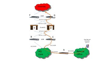
Routing • Determining the path that the packets should take in going from one host to another is called routing • A graph can be used to represent a network • The nodes correspond to the physical nodes and the edges correspond to the node connections 3 B C 5 2 A F 2 1 3 2 1 D E 1
Routing Algorithms • A the heart of the routing is the routing algorithm • There are two kinds of routing algorithms • A global routing algorithm uses the knowledge of the entire network while making selection • A decentralized algorithm calculates the least cost path in an iterative distributed manner • The routing algorithms can also be classified as • Static: Routes change very slowly over time usually via manual intervention • Dynamic: Change routing paths as network traffic loads or the topology changes
Routing Algorithms • Only two types of algorithms typically used on the Internet • A dynamic global link state algorithm • A dynamic decentralized distance vector algorithm
Hub, Switch and Router • Switch is a generic term for a device that switches data (packets or frames) • Hub is link layer switch (node to node) • Operates on ethernet frames • L2 switch • Uses physical addresses (mac addresses) • Bridge connects two LANS or two segments of the same LAN • Protocol Independent • Operates on ethernet frames • L2 switch • Uses physical addresses (mac addresses)
Hub, Switch and Router • Router is network layer switch (host to host) • Also called L3 switch • Uses network addresses • Operates on packets • Gateway is a generic term for an internetworking system • Can be implemented in software and/or hardware • Can operate at any level of the OSI model from application protocols to low-level signaling. • http://pcwebopedia.com
Routers • In TCP/IP any machine on the same network can be contacted directly, but machines on another network must be contacted through a router or gateway. • Router is a specific device (software or hardware) that forwards a transmission from a local network to other networks. • Since the router is another device on the network, it needs to have its own internal IP address that the computers can contact.