Download
1 / 30
300 likes | 357 Views
Learn about microprocessors, their arithmetic/logic operations, programming languages, and organization in a system. Explore inputs, outputs, and internal components like ALU, Control Unit, and Register Array.

E N D
What is a Microprocessor? • The word comes from the combination micro and processor. • Processor means a device that processes whatever. In this context processor means a device that processes numbers, specifically binary numbers, 0’s and 1’s. • To process means to manipulate. It is a general term that describes all manipulation. Again in this content, it means to perform certain operations on the numbers that depend on the microprocessor’s design.
Definition of the Microprocessor The microprocessor is a programmable device that takes innumbers, performs on them arithmetic or logical operations according to the programstored in memory and then producesother numbers as a result.
Definition (Contd.) • Arithmetic and Logic Operations: • Every microprocessor has arithmetic operations such as add and subtract as part of its instruction set. • Most microprocessors will have operations such as multiply and divide. • Some of the newer ones will have complex operations such as square root. • In addition, microprocessors have logic operations as well. Such as AND, OR, XOR, shift left, shift right, etc. • Again, the number and types of operations define the microprocessor’s instruction set and depends on the specific microprocessor.
Definition (Contd.) • Program: A program is a sequence of instructions that bring data into the microprocessor, processes it and sends it out. • There are many programming languages (C, C++, FORTRAN, and JAVA…) However, these programming languages can be grouped into three main levels (these days a fourth level is developing).
Definition (Contd.) • Programming Languages • Machine language • Machine language is the lowest level programming language. It is a language intended to be understood by the microprocessor (the machine) only.In this language, every instruction is described by binary patterns. e.g. 11001101 may mean 1 + 2 This is the form in which instructions are stored in memory. This is the only form that the microprocessor understands.
Definition (Contd.) • Programming Languages • Assembly language • This language is more understandable by humans. In this language, the binary patterns are assigned mnemonics (short abbreviated names). e.g. “Add 1,2” is assigned to the machine language pattern 11001101 mentioned above to refer to the operation 1+2. There is usually one assembly language instruction for each machine language instruction.
Definition (Contd.) • Programming Languages • High level languages • These are languages like C, PASCAL and FORTRON. These are more natural for humans to use than assembly or machine languages. They are also more compact (i.e. it takes less statements to write the program). One high level instruction translates into many assembly or machine language instructions. e.g. x = y + z may translate into:MOV 1000, R1MOV 1004, R2 ADD R1, R2 MOV R1, 1008
Definition (Contd.) • Programming Languages • The new level being developed: is ultra high level languages which would contain things like C++, and JAVA. • Here a single instruction may translate into hundreds of assembly or machine language instructions.
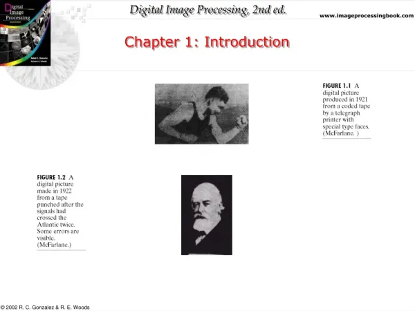
A Microprocessor-based system From the above description, we can draw the following block diagram to represent a microprocessor-based system Output Input Microprocessor Memory
Inside The Microprocessor • Internally, the microprocessor is made up of 3 main units. • The Arithmetic/Logic Unit (ALU) • The Control Unit. • An array of registers for holding data while it is being manipulated.
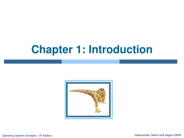
Organization of a microprocessor-based system • Let’s expand the picture a bit. I/O Input / Output Register Array ALU System Bus Control Memory ROM RAM
Organization of the Microprocessor • The microprocessor can be divided into three main pieces: • Arithmetic/Logic Unit • Performs all computing and logic operations such as addition and subtraction as well as AND, OR and XOR. • Register Array • A collection of registers within the microprocessor itself. These are used primarily for data storage during program execution. The number and the size of these registers differ from one microprocessor to the other. • Control Unit • As the name implies, the control Unit controls what is happening in the microprocessor. It provides the necessary control and timing signals to all operations in the microprocessor as well as its contact to the outside world.
I/O Input/Output • Input and output devices are the system’s means of communicating with the outside world. These devices are collectively known as peripherals. • Input devices transfer binary information from the outside world to the microprocessor. • Examples of input devices are: keyboard, mouse, bar code reader, scanner and the like. • Output devices transfer binary information from the microprocessor to the outside world. • Theses include things like an LED, a monitor, a printer and the like.
System Bus • A communication path between the microprocessor and peripherals. • It is simply a group of wires carrying the voltages and curents representing the different bit values. • The microprocessor communicates with only one peripheral at a time. • Controlling the bus is done by the Control Unit.
Microprocessor Architecture • The microprocessor can be programmed to perform functions on given data by writing specific instructions into its memory. • The microprocessor reads one instruction at a time, matches it with its instruction set, and performs the data manipulation specified. • The result is either stored back into memory or displayed on an output device.
The 8085 Architecture • The 8085 uses three separate busses to perform its operations • The address bus. • The data bus. • The control bus.
The Address Bus • 16 bits wide (A0 A1…A15) • Therefore, the 8085 can access locations with numbers from 0 to 65,536. Or, the 8085 can access a total of 64K addresses. • “Unidirectional”. • Information flows out of the microprocessor and into the memory or peripherals. • When the 8085 wants to access a peripheral or a memory location, it places the 16-bit address on the address bus and then sends the appropriate control signals.
The Data Bus • 8 bits wide (D0 D1…D7) • “Bi-directional”. • Information flows both ways between the microprocessor and memory or I/O. • The 8085 uses the data bus to transfer the binary information. • Since the data bus has 8-bits only, then the 8085 can manipulate data 8 bits at-a-time only.
The Control Bus • There is no real control bus. Instead, the control bus is made up of a number of single bit control signals.
The 8085 Microprocessor • The 8085 is an 8-bit microprocessor made by Intel. • It has: • 6 general purpose registers • An accumulator • A flag register • A stack pointer • A program counter Accumulator Flags B C D E H L Program Counter Stack Pointer
The ALU • In addition to the arithmetic & logic circuits, the ALU includes the accumulator, which is part of every arithmetic & logic operation. • Also, the ALU includes a temporary register used for holding data temporarily during the execution of the operation. This temporary register is not accessible by the programmer.
The Flags register • There is also the flags register whose bits are affected by the arithmetic & logic operations. • S-sign flag • The sign flag is set if bit D7 of the accumulator is set after an arithmetic or logic operation. • Z-zero flag • Set if the result of the ALU operation is 0. Otherwise is reset. This flag is affected by operations on the accumulator as well as other registers. (DCR B). • AC-Auxiliary Carry • This flag is set when a carry is generated from bit D3 and passed to D4 . This flag is used only internally for BCD operations. (Section 10.5 describes BCD addition including the DAA instruction). • P-Parity flag • After an ALU operation if the result has an even # of 1’s the p-flag is set. Otherwise it is cleared. So, the flag can be used to indicate even parity. • CY-carry flag • Discussed earlier
The Internal Architecture • The Stack pointer • The stack pointer is also a 16-bit register that is used to point into memory. • The memory this register points to is a special area called the stack. • The stack is an area of memory used to hold data that will be retreived soon. • The stack is usually accessed in a Last In First Out (LIFO) fashion.
Instruction with Immediate Date • Operation: Load an 8-bit number into the accumulator. • MVI A, 32 • Operation: MVI A • Operand: The number 32 • Binary Code: 0011 1110 3E 1st byte. 0011 0010 32 2nd byte.
Arithmetic Operations • Addition (ADD, ADI): • Any 8-bit number. • The contents of a register. • The contents of a memory location. • Can be added to the contents of the accumulator and the result is stored in the accumulator. • Subtraction (SUB, SUI): • Any 8-bit number • The contents of a register • The contents of a memory location • Can be subtracted from the contents of the accumulator. The result is stored in the accumulator.
Arithmetic Operations • Increment (INR) and Decrement (DCR): • The 8-bit contents of any memory location or any register can be directly incremented or decremented by 1. • No need to disturb the contents of the accumulator.
Logic Operations • These instructions perform logic operations on the contents of the accumulator. • ANA, ANI, ORA, ORI, XRA and XRI • Source: Accumulator and • An 8-bit number • The contents of a register • The contents of a memory location • Destination: Accumulator ANA R/M AND Accumulator With Reg/Mem ANI # AND Accumulator With an 8-bit number ORA R/M OR Accumulator With Reg/Mem ORI # OR Accumulator With an 8-bit number XRA R/M XOR Accumulator With Reg/Mem XRI # XOR Accumulator With an 8-bit number
Additional Logic Operations • Rotate • Rotate the contents of the accumulator one position to the left or right. • RLC Rotate the accumulator left. Bit 7 goes to bit 0AND the Carry flag. • RAL Rotate the accumulator left through the carry. Bit 7 goes to the carry and carry goes to bit 0. • RRC Rotate the accumulator right. Bit 0 goes to bit 7 AND the Carry flag. • RAR Rotate the accumulator right through the carry. Bit 0 goes to the carry and carry goes to bit 7.
RLC vs. RLA • RLC • RAL Carry Flag 7 6 5 4 3 2 1 0 Accumulator Carry Flag 7 6 5 4 3 2 1 0 Accumulator