Download
1 / 41
410 likes | 523 Views
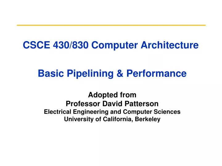
CSCE 430/830 Computer Architecture Basic Pipelining & Performance. Adopted from Professor David Patterson Electrical Engineering and Computer Sciences University of California, Berkeley. Outline. MIPS – An ISA for Pipelining 5 stage pipelining Structural and Data Hazards Forwarding

E N D
CSCE 430/830 Computer Architecture Basic Pipelining & Performance Adopted from Professor David Patterson Electrical Engineering and Computer Sciences University of California, Berkeley
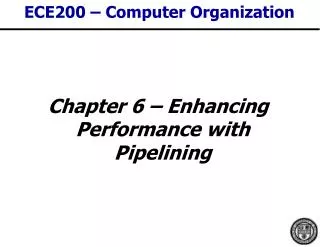
Outline • MIPS – An ISA for Pipelining • 5 stage pipelining • Structural and Data Hazards • Forwarding • Branch Schemes • Exceptions and Interrupts • Conclusion CSCE 430/830, Basic Pipelining & Performance
A "Typical" RISC ISA • 32-bit fixed format instruction (3 formats) • 32 32-bit GPR (R0 contains zero, DP take pair) • 3-address, reg-reg arithmetic instruction • Single address mode for load/store: base + displacement • no indirection • Simple branch conditions • Delayed branch see: SPARC, MIPS, HP PA-Risc, DEC Alpha, IBM PowerPC, CDC 6600, CDC 7600, Cray-1, Cray-2, Cray-3 CSCE 430/830, Basic Pipelining & Performance
Example: MIPS ( MIPS) Register-Register 6 5 11 10 31 26 25 21 20 16 15 0 Op Rs1 Rs2 Rd Opx Register-Immediate 31 26 25 21 20 16 15 0 immediate Op Rs1 Rd Branch 31 26 25 21 20 16 15 0 immediate Op Rs1 Rs2/Opx Jump / Call 31 26 25 0 target Op CSCE 430/830, Basic Pipelining & Performance
signals Datapath vs Control Datapath Controller • Datapath: Storage, FU, interconnect sufficient to perform the desired functions • Inputs are Control Points • Outputs are signals • Controller: State machine to orchestrate operation on the data path • Based on desired function and signals Control Points CSCE 430/830, Basic Pipelining & Performance
Approaching an ISA • Instruction Set Architecture • Defines set of operations, instruction format, hardware supported data types, named storage, addressing modes, sequencing • Meaning of each instruction is described by RTL (Register Transfer Language) on architected registers and memory • Given technology constraints assemble adequate datapath • Architected storage mapped to actual storage • Function units to do all the required operations • Possible additional storage (eg. MAR, MBR, …) • Interconnect to move information among regs and FUs • Map each instruction to sequence of RTLs • Collate sequences into symbolic controller state transition diagram (STD) • Lower symbolic STD to control points • Implement controller CSCE 430/830, Basic Pipelining & Performance
Adder 4 Address Inst ALU 5 Steps of MIPS DatapathFigure A.2, Page A-8 Instruction Fetch Instr. Decode Reg. Fetch Execute Addr. Calc Memory Access Write Back Next PC MUX Next SEQ PC Zero? RS1 Reg File MUX RS2 Memory Data Memory L M D RD MUX MUX Sign Extend IR <= mem[PC]; PC <= PC + 4 Imm WB Data Reg[IRrd] <= Reg[IRrs1] opIRop Reg[IRrs2] CSCE 430/830, Basic Pipelining & Performance
MEM/WB ID/EX EX/MEM IF/ID Adder 4 Address ALU 5 Steps of MIPS DatapathFigure A.3, Page A-9 Instruction Fetch Execute Addr. Calc Memory Access Instr. Decode Reg. Fetch Write Back Next PC MUX Next SEQ PC Next SEQ PC Zero? RS1 Reg File MUX Memory RS2 Data Memory RD MUX MUX IR <= mem[PC]; PC <= PC + 4 Sign Extend WB Data Imm A <= Reg[IRrs1]; B <= Reg[IRrs2] RD RD RD rslt <= A opIRop B WB <= result CSCE 430/830, Basic Pipelining & Performance Reg[IRrd] <= WB
jmp br LD RI r <= A + IRim r <= A opIRop IRim if bop(A,b) PC <= PC+IRim PC <= IRjaddr WB <= r WB <= Mem[r] Reg[IRrd] <= WB Reg[IRrd] <= WB Inst. Set Processor Controller IR <= mem[PC]; PC <= PC + 4 Ifetch opFetch-DCD A <= Reg[IRrs1]; B <= Reg[IRrs2] JSR JR ST RR r <= A opIRop B WB <= r Reg[IRrd] <= WB CSCE 430/830, Basic Pipelining & Performance
MEM/WB ID/EX EX/MEM IF/ID Adder 4 Address ALU 5 Steps of MIPS DatapathFigure A.3, Page A-9 Instruction Fetch Execute Addr. Calc Memory Access Instr. Decode Reg. Fetch Write Back Next PC MUX Next SEQ PC Next SEQ PC Zero? RS1 Reg File MUX Memory RS2 Data Memory MUX MUX Sign Extend WB Data Imm RD RD RD • Data stationary control • local decode for each instruction phase / pipeline stage CSCE 430/830, Basic Pipelining & Performance
Reg Reg Reg Reg Reg Reg Reg Reg Ifetch Ifetch Ifetch Ifetch DMem DMem DMem DMem ALU ALU ALU ALU Cycle 1 Cycle 2 Cycle 3 Cycle 4 Cycle 5 Cycle 6 Cycle 7 Visualizing PipeliningFigure A.2, Page A-8 Time (clock cycles) I n s t r. O r d e r CSCE 430/830, Basic Pipelining & Performance
Instruction-Level Parallelism • Review of Pipelining (the laundry analogy) CSCE 430/830, Basic Pipelining & Performance
Pipelining is not quite that easy! • Limits to pipelining: Hazards prevent next instruction from executing during its designated clock cycle • Structural hazards: HW cannot support this combination of instructions (single person to fold and put clothes away) • Data hazards: Instruction depends on result of prior instruction still in the pipeline (missing sock) • Control hazards: Caused by delay between the fetching of instructions and decisions about changes in control flow (branches and jumps). CSCE 430/830, Basic Pipelining & Performance
Reg Reg Reg Reg Reg Reg Reg Reg Reg Reg Ifetch Ifetch Ifetch Ifetch DMem DMem DMem DMem ALU ALU ALU ALU ALU One Memory Port/Structural HazardsFigure A.4, Page A-14 Time (clock cycles) Cycle 1 Cycle 2 Cycle 3 Cycle 4 Cycle 5 Cycle 6 Cycle 7 I n s t r. O r d e r Load DMem Instr 1 Instr 2 Instr 3 Ifetch Instr 4 CSCE 430/830, Basic Pipelining & Performance
Reg Reg Reg Reg Reg Reg Reg Reg Ifetch Ifetch Ifetch Ifetch DMem DMem DMem ALU ALU ALU ALU Bubble Bubble Bubble Bubble Bubble One Memory Port/Structural Hazards(Similar to Figure A.5, Page A-15) Time (clock cycles) Cycle 1 Cycle 2 Cycle 3 Cycle 4 Cycle 5 Cycle 6 Cycle 7 I n s t r. O r d e r Load DMem Instr 1 Instr 2 Stall Instr 3 How do you “bubble” the pipe? CSCE 430/830, Basic Pipelining & Performance
Speed Up Equation for Pipelining For simple RISC pipeline, CPI = 1: CSCE 430/830, Basic Pipelining & Performance
Example: Dual-port vs. Single-port • Machine A: Dual ported memory (“Harvard Architecture”) • Machine B: Single ported memory, but its pipelined implementation has a 1.05 times faster clock rate • Ideal CPI = 1 for both • Loads are 40% of instructions executed SpeedUpA = Pipeline Depth/(1 + 0) x (clockunpipe/clockpipe) = Pipeline Depth SpeedUpB = Pipeline Depth/(1 + 0.4 x 1) x (clockunpipe/(clockunpipe / 1.05) = (Pipeline Depth/1.4) x 1.05 = 0.75 x Pipeline Depth SpeedUpA / SpeedUpB = Pipeline Depth/(0.75 x Pipeline Depth) = 1.33 • Machine A is 1.33 times faster CSCE 430/830, Basic Pipelining & Performance
Reg Reg Reg Reg Reg Reg Reg Reg Reg Reg ALU ALU ALU ALU ALU Ifetch Ifetch Ifetch Ifetch Ifetch DMem DMem DMem DMem DMem EX WB MEM IF ID/RF I n s t r. O r d e r add r1,r2,r3 sub r4,r1,r3 and r6,r1,r7 or r8,r1,r9 xor r10,r1,r11 Data Hazard on R1Figure A.6, Page A-17 Time (clock cycles) CSCE 430/830, Basic Pipelining & Performance
Three Generic Data Hazards • Read After Write (RAW)InstrJ tries to read operand before InstrI writes it • Caused by a “Dependence” (in compiler nomenclature). This hazard results from an actual need for communication. I: add r1,r2,r3 J: sub r4,r1,r3 CSCE 430/830, Basic Pipelining & Performance
I: sub r4,r1,r3 J: add r1,r2,r3 K: mul r6,r1,r7 Three Generic Data Hazards • Write After Read (WAR)InstrJ writes operand before InstrI reads it • Called an “anti-dependence” by compiler writers.This results from reuse of the name “r1”. • Can it happen in MIPS 5 stage pipeline? • All instructions take 5 stages, and • Reads are always in stage 2, and • Writes are always in stage 5 CSCE 430/830, Basic Pipelining & Performance
I: sub r1,r4,r3 J: add r1,r2,r3 K: mul r6,r1,r7 Three Generic Data Hazards • Write After Write (WAW)InstrJ writes operand before InstrI writes it. • Called an “output dependence” by compiler writersThis also results from the reuse of name “r1”. • Can’t happen in MIPS 5 stage pipeline because: • All instructions take 5 stages, and • Writes are always in stage 5 • Will see WAR and WAW in more complicated pipes CSCE 430/830, Basic Pipelining & Performance
Reg Reg Reg Reg Reg Reg Reg Reg Reg Reg ALU ALU ALU ALU ALU Ifetch Ifetch Ifetch Ifetch Ifetch DMem DMem DMem DMem DMem I n s t r. O r d e r add r1,r2,r3 sub r4,r1,r3 and r6,r1,r7 or r8,r1,r9 xor r10,r1,r11 Forwarding to Avoid Data HazardFigure A.7, Page A-19 Time (clock cycles) CSCE 430/830, Basic Pipelining & Performance
ALU HW Change for ForwardingFigure A.23, Page A-37 ID/EX EX/MEM MEM/WR NextPC mux Registers Data Memory mux mux Immediate What circuit detects and resolves this hazard? CSCE 430/830, Basic Pipelining & Performance
Reg Reg Reg Reg Reg Reg Reg Reg Reg Reg ALU ALU ALU ALU ALU Ifetch Ifetch Ifetch Ifetch Ifetch DMem DMem DMem DMem DMem I n s t r. O r d e r add r1,r2,r3 lw r4, 0(r1) sw r4,12(r1) or r8,r6,r9 xor r10,r9,r11 Forwarding to Avoid LW-SW Data HazardFigure A.8, Page A-20 Time (clock cycles) Any hazard that cannot be avoided with forwarding? CSCE 430/830, Basic Pipelining & Performance
Reg Reg Reg Reg Reg Reg Reg Reg ALU Ifetch Ifetch Ifetch Ifetch DMem DMem DMem DMem ALU ALU ALU lwr1, 0(r2) I n s t r. O r d e r sub r4,r1,r6 and r6,r1,r7 or r8,r1,r9 Data Hazard Even with ForwardingFigure A.9, Page A-21 Time (clock cycles) CSCE 430/830, Basic Pipelining & Performance
Reg Reg Reg Ifetch Ifetch Ifetch Ifetch DMem ALU Bubble ALU ALU Reg Reg DMem DMem Bubble Reg Reg Data Hazard Even with Forwarding(Similar to Figure A.10, Page A-21) Time (clock cycles) I n s t r. O r d e r lwr1, 0(r2) How is this detected? sub r4,r1,r6 and r6,r1,r7 Bubble ALU DMem or r8,r1,r9 CSCE 430/830, Basic Pipelining & Performance
Software Scheduling to Avoid Load Hazards Fast code: LW Rb,b LW Rc,c LW Re,e ADD Ra,Rb,Rc LW Rf,f SW a,Ra SUB Rd,Re,Rf SW d,Rd Try producing fast code for a = b + c; d = e – f; assuming a, b, c, d ,e, and f in memory. Slow code: LW Rb,b LW Rc,c ADD Ra,Rb,Rc SW a,Ra LW Re,e LW Rf,f SUB Rd,Re,Rf SW d,Rd Compiler optimizes for performance. Hardware checks for safety. CSCE 430/830, Basic Pipelining & Performance
Outline • Review • Quantify and summarize performance • Ratios, Geometric Mean, Multiplicative Standard Deviation • F&P: Benchmarks age, disks fail,1 point fail danger • MIPS – An ISA for Pipelining • 5 stage pipelining • Structural and Data Hazards • Forwarding • Branch Schemes • Exceptions and Interrupts • Conclusion CSCE 430/830, Basic Pipelining & Performance
Reg Reg Reg Reg Reg Reg Reg Reg Reg Reg ALU ALU ALU ALU ALU Ifetch Ifetch Ifetch Ifetch Ifetch DMem DMem DMem DMem DMem 10: beq r1,r3,36 14: and r2,r3,r5 18: or r6,r1,r7 22: add r8,r1,r9 36: xor r10,r1,r11 Control Hazard on BranchesThree Stage Stall What do you do with the 3 instructions in between? How do you do it? Where is the “commit”? CSCE 430/830, Basic Pipelining & Performance
Branch Stall Impact • If CPI = 1, 30% branch, Stall 3 cycles => new CPI = 1.9! • Two part solution: • Determine branch outcome sooner, AND • Compute taken branch (target) address earlier • MIPS branch tests if register = 0 or 0 • MIPS Solution: • Move Zero test to ID/RF stage • Adder to calculate new PC in ID/RF stage • 1 clock cycle penalty for branch versus 3 CSCE 430/830, Basic Pipelining & Performance
MEM/WB ID/EX EX/MEM IF/ID Adder 4 Address ALU Pipelined MIPS DatapathFigure A.24, page A-38 Instruction Fetch Execute Addr. Calc Memory Access Instr. Decode Reg. Fetch Write Back Next SEQ PC Next PC MUX Adder Zero? RS1 Reg File Memory RS2 Data Memory MUX MUX Sign Extend WB Data Imm RD RD RD • Interplay of instruction set design and cycle time. CSCE 430/830, Basic Pipelining & Performance
Four Branch Hazard Alternatives #1: Stall until branch direction is clear #2: Predict Branch Not Taken • Execute successor instructions in sequence • “Squash” instructions in pipeline if branch actually taken • Advantage of late pipeline state update • 47% MIPS branches not taken on average • PC+4 already calculated, so use it to get next instruction #3: Predict Branch Taken • 53% MIPS branches taken on average • But haven’t calculated branch target address in MIPS • MIPS still incurs 1 cycle branch penalty • Other machines: branch target known before outcome CSCE 430/830, Basic Pipelining & Performance
Four Branch Hazard Alternatives #4: Delayed Branch • Define branch to take place AFTER a following instruction branch instruction sequential successor1 sequential successor2 ........ sequential successorn branch target if taken • 1 slot delay allows proper decision and branch target address in 5 stage pipeline • MIPS uses this Branch delay of length n CSCE 430/830, Basic Pipelining & Performance
becomes becomes becomes if $2=0 then add $1,$2,$3 if $1=0 then add $1,$2,$3 sub $4,$5,$6 add $1,$2,$3 if $1=0 then sub $4,$5,$6 Scheduling Branch Delay Slots (Fig A.14) A. From before branch B. From branch target C. From fall through add $1,$2,$3 if $1=0 then add $1,$2,$3 if $2=0 then • A is the best choice, fills delay slot • In B, the sub instruction may need to be copied, increasing IC • In B and C, must be okay to execute sub when branch fails sub $4,$5,$6 delay slot delay slot add $1,$2,$3 if $1=0 then sub $4,$5,$6 delay slot CSCE 430/830, Basic Pipelining & Performance
Delayed Branch • Compiler effectiveness for single branch delay slot: • Fills about 60% of branch delay slots • About 80% of instructions executed in branch delay slots useful in computation • About 50% (60% x 80%) of slots usefully filled • Delayed Branch downside: As processor go to deeper pipelines and multiple issue, the branch delay grows and need more than one delay slot • Delayed branching has lost popularity compared to more expensive but more flexible dynamic approaches • Growth in available transistors has made dynamic approaches relatively cheaper CSCE 430/830, Basic Pipelining & Performance
Evaluating Branch Alternatives Assume 4% unconditional branch, 6% conditional branch- untaken, 10% conditional branch-taken Scheduling Branch CPI speedup v. speedup v. scheme penalty unpipelined stall Stall pipeline 3 1.60 3.1 1.0 Predict taken 1 1.20 4.2 1.33 Predict not taken 1 1.14 4.4 1.40 Delayed branch 0.5 1.10 4.5 1.45 CSCE 430/830, Basic Pipelining & Performance
More branch evaluations • Suppose the branch frequencies (as percentage of all instructions) of 15% cond. Branches, 1% jumps and calls, and 60% cond. Branches are taken. Consider a 4-stage pipeline where branch is resolved at the end of the 2nd cycle for uncond. Branches and at the end of the 3rd cycle for cond. Branches. How much faster would the machine be without any branch hazards, ignoring other pipeline stalls? Pipeline speedupideal = Pipeline depth/(1+Pipeline stalls) = 4/(1+0) = 4 Pipeline stallsreal = (1x1%) + (2x9%) + (1x6%) = 0.24 Pipeline speedupreal = 4/(1+0.24) = 3.23 Pipeline speedupwithout controlhazards = 4/3.23 = 1.24 CSCE 430/830, Basic Pipelining & Performance
More branch question A reduced hardware implementation of the classic 5-stage RISC pipeline might use the EX stage hardware to perform a branch instruction comparison and then not actually deliver the branch target PC to the IF stage until the clock cycle in which the branch reaches the MEM stage. Control hazard stalls can be reduced by resolving branch instructions in ID, but improving performance in one aspect may reduce performance in other circumstances. How does determining branch outcome in the ID stage have the potential to increase data hazard stall cycles? CSCE 430/830, Basic Pipelining & Performance
Problems with Pipelining • Exception: An unusual event happens to an instruction during its execution • Examples: divide by zero, undefined opcode • Interrupt: Hardware signal to switch the processor to a new instruction stream • Example: a sound card interrupts when it needs more audio output samples (an audio “click” happens if it is left waiting) • Problem: It must appear that the exception or interrupt must appear between 2 instructions (Ii and Ii+1) • The effect of all instructions up to and including Ii is totally complete • No effect of any instruction after Ii can take place • The interrupt (exception) handler either aborts program or restarts at instruction Ii+1 CSCE 430/830, Basic Pipelining & Performance
Precise Exceptions in Static Pipelines Key observation: architected state only change in memory and register write stages. CSCE 430/830, Basic Pipelining & Performance
And In Conclusion: Control and Pipelining • Quantify and summarize performance • Ratios, Geometric Mean, Multiplicative Standard Deviation • F&P: Benchmarks age, disks fail,1 point fail danger • Next time: Read Appendix A, record bugs online! • Control VIA State Machines and Microprogramming • Just overlap tasks; easy if tasks are independent • Speed Up Pipeline Depth; if ideal CPI is 1, then: • Hazards limit performance on computers: • Structural: need more HW resources • Data (RAW,WAR,WAW): need forwarding, compiler scheduling • Control: delayed branch, prediction • Exceptions, Interrupts add complexity • Next time: Read Appendix C, record bugs online! CSCE 430/830, Basic Pipelining & Performance