Download

1 / 57
590 likes | 772 Views
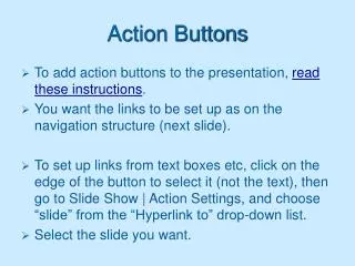
The HAAS Control Series. DISPLAY BUTTONS. Slide Legend. PRESS THREE TIMES TO GET TO THIS PAGE (Continued on next slide) Note:. To advance through the presentation click on your left mouse button or press < ENTER >. To exit press < ESC >. ACTIONS. KEYS. INSTRUCTIONS.

E N D
The HAAS Control Series DISPLAYBUTTONS
Slide Legend PRESS THREE TIMES TO GET TO THIS PAGE (Continued on next slide) Note: To advance through the presentation click on your left mouse button or press <ENTER>. To exit press <ESC>. ACTIONS KEYS INSTRUCTIONS INFORMATION OTHER INFORMATION
DISPLAY BUTTONS This moduleis intendedto provide youwith a familiarization of theDisplay Buttonson theHaas Control
PROGRAM CONVERSATIONAL: POSITION: OFFSETS: CURRENT COMMANDS: ALARMS or MESSAGES: PARAMETERS or DIAGNOSTICS: SETTINGS or GRAPHICS: HELP or CALCULATE: Display Buttons
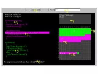
PROGRAM display will show the currently selected program. In the top left corner of the screen, you will see the title of the Display and (Mode) you are in. In the center of the screen, you will see the program number and the sequence number that was last executed, on the program you’re presently running (If your lines of code are numbered). Program/Conversational: PROGRAM (MEM) O91002 N00000 O91002 ; (Mill Engraving HAAS Logo) ; T1 M06 (TOOL#1 – ENGRAVING TOOL) ; G90 G54 G00 X-0.7355 Y0.429 ; S5000 M03 ; G00 G43 H01 Z1. M08 ; G01 Z0.03 F100. ; G91 ; G01 Z-0.0337 F7. ; G01 X-0.5687 Y-0.9857 ; G01 X-0.2275 ; G01 X0.1314 Y0.2275 ; G01 X-0.7835 ; G01 X0.1314 Y0.2275 ; G01 X0.7835 ; G01 X0.3058 Y0.5308 ; G01 X0.2275 ; G00 Z0.03375 ; F4 FOR PROG REVIEW
Program Conversational Button: PROGRAM (MEM) O91002 N0000 While running a program, you can review it with the PROGRAM REVIEW feature. To select Program Review while running a program, when you’re in the Program display PRESS The program will come up on both sides of the screen. On the left you will see 18 blocks of the program that is running and on the right you will see the same program that you can cursor through and review. To switch back PRESS again. G01 Z-0.0337 F7. ; O91002 ; G01 X-0.5687 Y-0.9857 ; (Mill Engraving HAAS Logo) ; G01 X-0.2275 ; T1 M06 (TOOL#1 – ENGRAVING TOOL) ; G01 X0.1314 Y0.2275 ; G90 G54 G00 X-0.7355 Y0.429 ; G01 X-0.2275 ; S5000 M03 ; G01 X0.1314 Y0.2275 ; G00 G43 H01 Z1. M08 ; G01 X-0.7835 ; G01 Z0.03 F100. ; G01 X0.1314 Y0.2275 ; G91 ; G01 X0.7835 ; G01 Z-0.0337 F7. ; G01 X-0.5687 Y-0.9857 ; G01 X-0.5687 Y-0.9857 ; G01 X-0.2275 ; G01 X-0.2275 ; G01 X0.1314 Y0.2275 ; G01 X0.1314 Y0.2275 ; G01 X-0.7835 ; G01 X-0.7835 ; G01 X0.1314 Y0.2275 ; G01 X0.1314 Y0.2275 ; G01 X0.7835 ; G01 X0.7835 ; G01 X0.3058 Y0.5308 ; G01 X0.3058 Y0.5308 ; G01 X0.2275 ; G01 X0.2275 ; G03 X0.2475 Y0.5508 R0.02 ; G00 Z0.03375 ; RUNNING F4 FOR NORMAL PROG
Program Conversational Button: BGEDITOR (MEM) O91002 N0000 While running a program, you can bring up that program or another to edit using the Background Edit feature. Type in the program number of the program you want to edit then PRESS Note; The program you are running is replaced with the program you want to edit. The original program is still running in the background. O91002 ; (Mill Engraving HAAS Logo) ; T1 M06 (TOOL#1 – ENGRAVING TOOL) ; G90 G54 G00 X-0.7355 Y0.429 ; S5000 M03 ; G00 G43 H01 Z1. M08 ; G01 Z0.03 F100. ; G91 ; G01 Z-0.0337 F7. ; G01 X-0.5687 Y-0.9857 ; G01 X-0.2275 ; G01 X0.1314 Y0.2275 ; G01 X-0.7835 ; G01 X0.1314 Y0.2275 ; G01 X0.7835 ; G01 X0.3058 Y0.5308 ; G01 X0.2275 ; G00 Z0.03375 ; F4 FOR PROG REVIEW RUNNING PROG EXISTS FEED
Program Conversational Button: BGEDITOR (MEM) O91002 N0000 You may perform any of the edit operations available in the Edit Mode. Insert, Alter, Delete and Undo. (Block Edit and Advanced Editor are not available) If editing the program you are running, no changes will be in effect until the program reaches the M30 command or you press<RESET>. PRESS To return to the running program. O91002 ; (Mill Engraving HAAS Logo) ; T1 M06 (TOOL#1 – ENGRAVING TOOL) ; G90 G54 G00 X-0.7355 Y0.429 ; S5000 M03 ; G00 G43 H01 Z1. M08 ; G01 Z0.03 F100. ; G91 ; G01 Z-0.0337 F7. ; G01 X-0.5687 Y-0.9857 ; G01 X-0.2275 ; G01 X0.1314 Y0.2275 ; G01 X-0.7835 ; G01 X0.1314 Y0.2275 ; G01 X0.7835 ; G01 X0.3058 Y0.5308 ; G01 X0.2275 ; G00 Z0.03375 ; F4 FOR PROG REVIEW RUNNING PROG EXISTS FEED
Position Button: POSITION (MEM) O91002 N0000 POSITION display will display five different pages that list the machine axes positions. or to scroll through the following pages: Operators, Work, Machine and Distance-to-Go. The fifth page shows all four in a small format. (OPERATOR) (WORK G54) X 0.0000 in X -9.0000 in Y 0.0000 in Y -7.0000 in Z 3.5179 in Z 3.5179 in (MACHINE) (DIST TO GO) X 0.0000 in X 0.0000 in Y 0.0000 in Y 0.0000 in Z 3.5179 in Z 0.0000 in
Position Button: POS-OPER (MEM) O91002 N0000 PAGE to POS-OPER. This is a reference display only. Each axis can be zeroed out independently; then subsequent moves will be shown relative to where you zeroed the axis. PRESS the X, YorZKeys and then <ORIGIN> to zero that axis. Or, in Handle Jog mode, PRESS X, YorZJOGKeys then <ORIGIN> to zero that axis. You can enter in an axis letter and number (X-1.25) and PRESS <ORIGIN> to have that value entered in that axis display. X 0.0000 in Y 0.0000 in Z 3.5179 in
Position Button: POS-WORK (MEM) O91002 N0000 PAGE to POS-WORK display. This position tells how far away the tool is in the X, Y and Z axes from the presently selected work zero point. X -9.0000 in Y -7.0000 in Z 3.5179 in
Position Button: POS-MACH (MEM) O91002 N0000 PAGE to the POS-MACH display. This is in reference to machine home. X -9.0000 in Y -7.0000 in Z 3.5179 in
Position Button: POS-TO-GO (MEM) O91002 N0000 PAGE to the POS-TO-GO display. When running or in Feed Hold, this incrementally displays the travel distance remaining in the program being run. When in Handle Jog, this display will show the total distance moved since selecting Handle Jog. Switching to a different Mode and back into Handle Jog will zero out all axes in the display and begin showing the distance moved. X 0.0000 in Y 0.0000 in Z 0.0000 in
Position Button: POSITION (MEM) O91002 N0000 (OPERATOR) (WORK G54) X 0.0000 in X -9.0000 in Y 0.0000 in Y -7.0000 in Z 3.5179 in Z 3.5179 in (MACHINE) (DIST TO GO) X 0.0000 in X 0.0000 in Y 0.0000 in Y 0.0000 in Z 3.5179 in Z 0.0000 in PAGE to the POSITION display. This page will show all of the displays together.
Offset Button: OFFSET (MEM) O91002 N0000 OFFSET can be used to display either the Tool Offsets or Work Offsets.You can toggle between the two screens by pressing the <OFFSET> key again. Programmable coolant position can be set by: Highlighting the CLNT POS column for the tool you want to set. TYPE in the number and PRESS<F1> this will replace the selected number with the number entered. Tool size can be in Radius or Diameter selectable with Setting 40. You can display up-to 200 different tools as determined by Setting 90. COOLANT ----LENGTH---- ----RADIUS---- TOOL POSITION GEOMETRY WEAR GEOMETRY WEAR FLUTES 1 4 -11.1234 0. 0. 0. 2 0 0. 0. 0. 2 3 0 0. 0. 0. 0. 2 4 0 0. 0. 0. 0. 2 5 0 0. 0. 0. 0. 2 6 0 0. 0. 0. 0. 2 7 0 0. 0. 0. 0. 2 8 0 0. 0. 0. 0. 2 9 0 0. 0. 0. 0. 2 10 0 0. 0. 0. 0. 2 11 0 0. 0. 0. 0. 2 12 0 0. 0. 0. 0. 2 13 0 0. 0. 0. 0. 2 14 0 0. 0. 0. 0. 2 15 0 0. 0. 0. 0. 2 CLNT POS WRITE ADD/F1 SET/OFSET TOGGLE 2 3 -11.4567
Offset Button: OFFSET OFFSET (JOG) O91002 N0000 TOOL LENGTH OFFSETS: PRESS PRESS Use the keys to select the jog rate and jog the tip of the tool (Z-axis) to the part zero surface. PRESS PRESS Continue with this sequence for all tools. COOLANT ----LENGTH---- ----RADIUS---- TOOL POSITION GEOMETRY WEAR GEOMETRY WEAR FLUTES 1 4 -11.1234 0. 0. 0. 2 0. 0. 0. 2 3 0 0. 0. 0. 0. 2 4 0 0. 0. 0. 0. 2 5 0 0. 0. 0. 0. 2 6 0 0. 0. 0. 0. 2 7 0 0. 0. 0. 0. 2 8 0 0. 0. 0. 0. 2 9 0 0. 0. 0. 0. 2 10 0 0. 0. 0. 0. 2 11 0 0. 0. 0. 0. 2 12 0 0. 0. 0. 0. 2 13 0 0. 0. 0. 0. 2 14 0 0. 0. 0. 0. 2 15 0 0. 0. 0. 0. 2 Z POSITION: -11.4567 WRITE ADD/F1 SET/OFSET TOGGLE JOGGING Z AXIS HANDLE .01 2 3 -11.4567
Offset Button: OFFSET OFFSET (JOG) O91002 N0000 WORK ZERO OFFSETS: PRESS PRESS andCURSORto the selected Work Zero Set Use the.1, .01, .001and.0001keys to select the jog rate and jog in the X-axis to the desired location. PRESS Repeat the process for the Y-axis. The Z-axis is normally zero but may be entered manually. If you have a 4th or 5th axis, additional columns will appear on this page. You can set the offsets as with the X-axis. G CODE X Y Z G 52 0. 0. 0. G 54 0. 0. G 55 0. 0. 0. G 56 0. 0. 0. G 56 0. 0. 0. G 58 0. 0. 0. G 59 0. 0. 0. G154 P1 0. 0. 0. (G110) G154 P2 0. 0. 0. (G111) G154 P3 0. 0. 0. (G112) G154 P4 0. 0. 0. (G113) G154 P5 0. 0. 0. (G114) G154 P6 0. 0. 0. (G115) G154 P7 0. 0. 0. (G116) G154 P8 0. 0. 0. (G116) X POSITION: -9.0000 WRITE ADD/F1 SET/OFSET TOGGLE JOGGING Z AXIS HANDLE .01 WORK ZERO OFFSET -9.0000
Current Commands Button: COMMAND (MEM) O91002 N00000 MACHINE coordinates – Press / CURRENT COMMANDS displays the current program, modal program commands, position, load, coolant level and tool, gearbox and spindle information. Press Page Up or Page Down to scroll through the following pages: Modal Values, System Timers, Macro Variables, Maintenance, Tool Life, and Tool Load. 0.0000 in 0.0000 in O91002 ; 0.0000 in (Mill Engraving HAAS Logo) ; T1 M06 (Tool #1 Engraving Tool) ; G00 G49 G69D00 PGM F0. G90 G54 G00 X-0.7355 Y0.4929 ; G17 G80H00 ACT F0. S5000 M03 ; G90 G98M00 PGM S0 G00 G43 H01 Z1. M08 ; G90 G98M00 PGM S0 G01 Z0.03 F100. ; G20 G54ACT S0 G91 ; G40 G64 CLNT POS G01 Z-0.0337 F7. ; G01 X-0.5687 Y-0.9857 ; SP LD: 0% G01 X-0.2275 ; X LOAD: 0% G01 X0.1314 Y-0.9857 ; Y LOAD: 0% G01 X-0.7835 ; Z LOAD: 0% G01 X0.1314 Y0.2275 ; Surf Spd 0 fpm Chip Load 0.0000 G01 X0.7835 ; TOOL 1 IN SPINDLE LOW GEAR STOP X CURRENT PROGRAM Y Z FD 0.0 SP 0
Current Commands Button: COMMAND (MEM) O91002 N00000 PRESS MODAL VALUES display shows current values of address codes and modal command codes in effect. • G01 N0 M03 O0000 • G17 X-0.62. S5000 A0. • G90 Y1.123 T1 B0. • G94 Z-0.25 F15. C0. • G20 I0. D00 U0. • G40 J0. H1 V0. • G49 K0. L1 W0. • G89 P0 E0. • G98 Q0. • G50 R0. • G54 • G64 • G69 CURRENT DISPLAY COMMAND
Current Commands Button: COMMAND (MEM) O91002 N00000 PRESS SYSTEM TIMERS displays POWER ON TIME, CYCLE START TIME, FEED CUTTING TIME, THIS CYCLE TIME, LAST CYCLE TIME, M30 COUNT #1 and M30 COUNT #2. Use the Cursor to highlight then PRESS to clear the selected display. THIS and LAST CYCLE cannot be cleared. • 542:21:0 • 1:23:45 • 0:56:12 • M30 COUNT #1 1 THIS CYCLE 1:45:67 • M30 COUNT #2 36 LAST CYCLE 1:45:56 POWER ON TIME CYCLE START TIME FEED CUTTING TIME
Current Commands Button: COMMAND (MEM) O91002 N00000 PRESS MACRO VARIABLES shows current values of Macro variables 1-33 and 100-199, 500-699, and 800-999. Use the Up and Down cursor keys to scan through more Macro pages. • MACRO VARIABLES G65 LEVEL = 0 • VAR.----VALUE VAR.-----VALUE VAR.----VALUE VAR.----VALUE • 1 17 33 • 2 18 • 3 19 • 4 20 • 5 21 • 6 22 • 7 23 • 8 24 • 9 25 • 10 26 • 11 27 • 12 28 • 13 29 • 14 30 • 15 31 • 16 32
Current Commands Button: COMMAND (MEM) O91002 N00000 PRESS MAINTENANCE display provides the operator reminders for routine maintenance. To activate: PRESS Active items will display the remaining hours till maintenance is due. The message MAINTENANCE DUE is displayed at the bottom of the screen when the time reaches zero. No alarm is generated. - to select, ORIGIN to change, <> to adjust Remaining Hours AIR FILTER in control enclosure - replace 250 ON-TIME OIL FILTER - replaced 250 ON-TIME GEARBOX OIL - replaced 1800 ON-TIME COOLANT TANK – check level, leakage, oil in coolant 10 ON-TIME WAY LUBE SYSTEM – check level 50 CS-TIME GEARBOX OIL – check level 250 ON-TIME SEALS/WHIPERS missing, torn, leaking - check 50 CS-TIME AIR SUPPLY FILTER – check for water 10 ON-TIME HYDRAULIC OIL – check level 250 ON-TIME MAINTENANCE COOLANT - Needs replacement 100 ON-TIME MONITORING STARTED WITH DEFAULT HOURS
Current Commands Button: COMMAND (MEM) O91002 N00000 PRESS again to deactivate. PRESS again to Reset. Default values are set by the software but can be changed using the Left and Right arrow cursors. - to select, ORIGIN to change, <> to adjust Remaining Hours AIR FILTER in control enclosure - replace -- ON-TIME OIL FILTER - replaced -- ON-TIME GEARBOX OIL - replaced -- ON-TIME COOLANT TANK – check level, leakage, oil in coolant -- ON-TIME WAY LUBE SYSTEM – check level -- CS-TIME GEARBOX OIL – check level -- ON-TIME SEALS/WHIPERS missing, torn, leaking - check -- CS-TIME AIR SUPPLY FILTER – check for water -- ON-TIME HYDRAULIC OIL – check level -- ON-TIME MAINTENANCE -- ON-TIME COOLANT - Needs replacement MONOTORING STOPPED
Current Commands Button: COMMAND (MEM) O91002 N00000 PRESS TOOL LIFEdisplays the number of times a tool is used (selected). Placing a number in the Alarm column sets the number of times the tool can be selected before an Alarm is generated. Highlight the number and PRESS to clear the selected display. Place the cursor at the top of the column and PRESS to clear the whole column. • FEED TIME TOTAL TIME USAGE ALARM • 0:00:00 0:00:00 0 • 2 0:00:00 0:00:00 0 0 • 3 0:00:00 0:00:00 0 0 • 4 0:00:00 0:00:00 0 0 • 5 0:00:00 0:00:00 0 0 • 6 0:00:00 0:00:00 0 0 • 7 0:00:00 0:00:00 0 0 • 8 0:00:00 0:00:00 0 0 • 9 0:00:00 0:00:00 0 0 • 10 0:00:00 0:00:00 0 0 • 11 0:00:00 0:00:00 0 0 • 12 0:00:00 0:00:00 0 0 • 13 0:00:00 0:00:00 0 0 • 14 0:00:00 0:00:00 0 0 • 15 0:00:00 0:00:00 0 0 • 16 0:00:00 0:00:00 0 0 TOOL LIFE 1 10
Current Commands Button: COMMAND (MEM) O91002 N00000 PRESS TOOL LOAD displays the Maximum Spindle Load each tool has generated. Use the Limit % column to set the max load for that tool. When the load is reached or exceeded the machine will alarm. PRESS <ORIGIN> to clear the selected display. Place the cursor at the top of the column and PRESS <ORIGIN> to clear the column. Setting 84 can change the Overload Action. VIBRATION monitoring is not yet active. • VIBRATION • TOOL MAX % LIMIT % MAX (G) LIMIT (G) • 0% 0.00 0.00 TOOL 1 IN SPINDLE • 2 0% 0% 0.00 0.00 SP LOAD: 0% • 3 0% 0% 0.00 0.00 Vibration: NO SENSOR • 4 0% 0% 0.00 0.00 • 5 0% 0% 0.00 0.00 X LOAD: 0% • 6 0% 0% 0.00 0.00 Y LOAD: 0% • 7 0% 0% 0.00 0.00 Z LOAD: 0% • 8 0% 0% 0.00 0.00 • 9 0% 0% 0.00 0.00 • 10 0% 0% 0.00 0.00 • 11 0% 0% 0.00 0.00 • 12 0% 0% 0.00 0.00 • 13 0% 0% 0.00 0.00 • 14 0% 0% 0.00 0.00 • 15 0% 0% 0.00 0.00 SPINDLE LOAD 1 0% MAX-Highest value since origin LIMIT-Value before warning issue. Press ORIGIN to zero out values
Current Commands Button: COMMAND (MEM) O91002 N00000 BAR FEEDER display if a Bar Feeder is installed. This display would appear after the MAINTENANCE page. It is used for entering the Servo Bar 300 variables. Refer to the Servo Bar 300 Operator’s Manual for more information. 3100 PART LENGTH + CUTOFF : x x . x x x x IN 3101 INITIAL PUSH LENGTH : x x . x x x x IN 3102 MIN CLAMP LENGTH : x x . x x x x IN 3103 MAX # PARTS : x x x 3104 MAX # BARS : x x x 3105 MAX LENGTH TO RUN : x x x . x x x x IN 3106 CURRENT # PARTS RUN : x x x 3107 CURRENT # BARS RUN : x x x 3108 CURRENT LENGTH RUN : x x x . x x x x IN 3109 LENGTH OF LONGEST BAR : x x . x x x x IN 3110 CURRENT BAR LENGTH : x x . x x x x IN 3113 MIN RETRACT POSITION : x . x x x x IN HAAS SERVO BAR:
Current Commands Button: COMMAND (MEM) O91002 N00000 PALLET SCHEDULE TABLE Display if machine is equipped with a pallet changer. It assists the operator in scheduling and tracking of pallets during production. Refer to the APC Operator’s Manual for information on its use. PALLET LOAD PALLET PALLET PROGRAM PROGRAM NUMBER ORDER STATUS USAGE NUMBER COMMENT 1 1 SCHEDULED 0 O01234 FIRST OPERATION 2 0 UNSCHEDULED 0 3 2 SCHEDULED 0 O03456 SECOND OPERATION 4 3 SCHEDULED 0 O90871 ROTARY PALLET SCHEDULE TABLE 0 UNSCHEDULED 1 SCHEDULED 2 LOADED 3 COMPLETED 4 USER 5 USER
Current Commands Button: COMMAND (MEM) O91002 N00000 LASER display is the equivalent of a tool table for the Laser machines. For setting up the various values of address codes and modal command codes in effect. LASER CUTTING DATA GENERAL INFORMATION LASER DATA # : 1 DESCRIPTION : Cold Rolled Steel .030” . FOR CUTTING SMALL FEATURES OPERATOR INFORMATION MATERIAL THICKNESS : 0.0300 FEED RATE : 100 METHOD : FREQ. BURN THROUGH DATA BURN TIME (SEC) : 2.000 FREQUENCY (Hz) : 2000 POWER (W) : 10.000 GAS : AIR PRESSURE (PSI) : 100.000 CUT DATA PULSE FREQUENCY (Hz) : 1000 MINIMUM POWER (W) : 2.000 MAXIMUM POWER (W) : 20.000 ASSIST GAS : O2 ASSIST PRESSURE (PSI) : 0.000
Help/Calculate Button: HELP (MEM) O91002 N00000 HELP is a mini-manual. Use the Up and Down arrow keys to scroll through each section of the manual. You can use the PAGE UP/DOWN keys to move between the different sections. HELP FUNCTION 18-MAR-02 The help function is a mini-manual that will explain the functions of this Machine. To use it, push the cursor down or PAGE DOWN arrow on the cursor pad to scan through the manual or use the directory to select a topic. Each topic of the directory is preceded by an alphabetic letter. After finding a topic, press the letter on the keypad and the display will change to the topic and the explanation. Pushing the letter D will bring you to the directory. Pushing the help button again will select the calculator functions. To exit the help functions, select any other display. (MORE IN THIS SECTION)
Help/Calculate Button: HELP (MEM) O91002 N00000 PRESS the letter “D” or to bring up a Directory. To select a topic, type the letter next to the topic in the Help Directory. A…STARTUP AND RUNNING N…SET UP PROCEDURES B…PROG. REVIEW/DNC/BGEDIT/POWER DOWN O…OVERIDES C…G/M/S/T COMMAND CODES P…PARAMETERS / DIAGNOSTICS D…RETURN TO THIS DIRECTORY Q…POSITION DISPLAYS E…EDITING PROGRAMS R…RECV / SEND PROGRAMS F…SETTING PAGE S…SAMPLE PROGRAMS G…SPECIAL G CODES T…TOOL OFS/TOOL LIFE/LOAD H…TROUBLE SHOOTING U…GRAPHIC FUNCTION I…MDI / MANUAL DATA INPUT V…TOOL CHANGER J…JOGGING / HANDLE FUNCTION W…WORK COORDINATES K…CRT DISPLAY / KEYBOARD X…CREATING PROGRAMS L…ALARMS / MESSAGES Y…SPECIAL FUNCTIONS M…MAINTENANCE REQUIREMENTS Z…ZERO RETURN STARTUP AND RUNNING DIRECTORY
Help/Calculate Button: HELP (MEM) O91002 N00000 CALCULATOR (NO SOULTION YET) (MACHINE) ANGLE 1 . ANGLE 3 X 0.0000 in. ANGLE 2 . Y 0.0000 in. ANGLE 3 . SIDE 2 SIDE 1 Z 3.5179 in. SIDE 1 . SIDE 2 . ANGLE 1 ANGLE 2 SIDE 3 . SIDE 3 F3 Copies calculator value to highlighted filed in this or other calculator screens. F3 also copies calculator value to the data entry line of edit screens. F4 copies highlighted data to the calculator field. The bottom row of Display keys are all dual function.A second press of the key will bring up the second Display function. CALCULATE display includes 5 different Calculator Screens. Trigonometry, Circular, Milling/Tapping, Circle-Line Tangent and Circle-Circle Tangent calculators. You use the <PAGE UP> or<PAGE DOWN> keys to navigate between the screens. You can transfer a calculated value to a highlighted field by pressing <F3>. You can copy a value from a field to the calculator by pressing <F4>. 0.000000000 LOAD
Help/Calculate Button: HELP (MEM) O91002 N00000 CALCULATOR (NO SOULTION YET) (MACHINE) ANGLE 1 45.0000 ANGLE 3 X 0.0000 in. ANGLE 2 25.0000 Y 0.0000 in. ANGLE 3 110.000 SIDE 2 SIDE 1 Z 3.5179 in. SIDE 1 .7524 SIDE 2 .4497 ANGLE 1 ANGLE 2 SIDE 3 1.0000 SIDE 3 F3 Copies calculator value to highlighted filed in this or other calculator screens. F3 also copies calculator value to the data entry line of edit screens. F4 copies highlighted data to the calculator field. All five displays have calculators in the upper left corner. All have an equivalent solver. You enter known values into each cursor selected field; when enough data is entered the control will calculate the remaining fields and the geometry will be displayed. You cannot Overwrite a highlighted field as they are calculated values. 0.000000000 LOAD ANGLE 3 SIDE 1 SIDE 2
Help/Calculate Button: HELP (MEM) O91002 N00000 PRESS To get to the Circular Calculator This display is for circular motion problems. Enter the known values and when enough data is entered the control will solve the remaining values. CALCULATOR (NO SOULTION YET) CENTER X . CENTER Y . START X . (MACHINE) START Y . X 0.0000 in. END X . Y 0.0000 in. END Y . Z 3.5179 in. RADIUS . ANGLE . DIRECTION CW 0.000000000 LOAD
Help/Calculate Button: HELP (MEM) O91002 N00000 PRESS To get to the Circular Calculator This display is for circular motion problems. Enter the known values and when enough data is entered the control will solve the remaining values. CALCULATOR CENTER X 1 . 0 0 0 0 CENTER Y 3 . 0 0 0 0 START X 1 . 5 0 0 0 (MACHINE) START Y 3 . 0 0 0 0 X 0.0000 in. 1 . 3 5 3 6 Y 0.0000 in. 3 . 3 5 3 6 Z 3.5179 in. 0 . 5 0 0 0 ANGLE 4 5 . 0 0 0 DIRECTION CCW G90 G3 X1.3536 Y3.3536 I-0.5 J0. G90 G3 X1.3536 Y3.3536 R0.5 G91 G3 X-0.1464 Y0.3536 I-0.5 J0. G91 G3 X-0.1464 Y0.3536 R0.5 0.000000000 E LOAD END X END Y RADIUS S
Help/Calculate Button: HELP (MEM) O91002 N00000 PRESS to transfer the code to the buffer at the bottom of the selected screen. PRESS to add it to the program. G90 G3 X1.3536 Y3.3536 I-0.5 J0. ; ; G90 G3 X1.3536 Y3.3536 I-0.5 J0.
Help/Calculate Button: HELP (MEM) O91002 N00000 MILLING/TAPPING will help solve for SFM, RPM, Feed Rate (for Milling and Tapping), Chip Load, and Horsepower. It also has aMaterials list thatprovides recommended surface speedsandchip loads. You can use to transfer data from the fields to the calculator. CALCULATOR 0.000000000 CUTTER DIA . IN SURFACE SPEED . FT/MIN RPM . (MACHINE) FLUTES . X 0.0000 in. FEED . IN/MIN Y 0.0000 in. CHIP LOAD . IN Z 3.5179 in. MATERIAL PRESS < or > FOR MATERIALS TAPPING THREAD . RPM . FEED . MILLING . LOAD
Help/Calculate Button: HELP (MEM) O91002 N00000 PRESS to the MATERIAL field. PRESS to bring up LOW CARBON UNALLOYED STEEL. Notice that four additional fields have appeared and recommended SFM and CHIP LOAD are flashing. These will stop flashing when you enter acceptable values in the respective fields. There are two TOOL TYPES and 21 different types of MATERIALS. CALCULATOR 0.000000000 CUTTER DIA . IN SURFACE SPEED . FT/MIN RECOMMENDED RPM . (MACHINE) FLUTES . X 0.0000 in. FEED . IN/MIN Y 0.0000 in. CHIP LOAD . IN RECOMMENDED Z 3.5179 in. MATERIAL TOOL TYPE CARBIDE CUT WIDTH . REQUIRED POWER 0.0 HP CUT DEPTH . TAPPING THREAD . RPM . FEED . MILLING 450 TO 650 LOAD 0.003 TO 0.006 LOW CARBON UNALLOYED STEEL
Help/Calculate Button: HELP (MEM) O91002 N00000 CIRCLE LINE TANGENT isused to calculate tangent points. After you enter the required data points, you will get the tangent coordinates and the Radius. CALCULATOR 0.000000000 (NO SOLUTION YET) POINT A X . Y . POINT B X . (MACHINE) Y . X 0.0000 in. POINT C X . Y 0.0000 in. Y . Z 3.5179 in. RADIUS . TGNT PT X . TGNT PT Y . CIRCLE LINE TANGENT . LOAD B C A
Help/Calculate Button: HELP (MEM) O91002 N00000 CIRCLE LINE TANGENT isused to calculate tangent points. After you enter the required data points, you will get the tangent coordinates and the Radius. CALCULATOR 0.000000000 POINT A X 1 . 1 2 5 0 Y 0 . 2 5 0 0 POINT B X - 0 . 3 7 5 0 (MACHINE) Y 2 . 3 5 0 0 X 0.0000 in. POINT C X 0 . 2 5 0 0 Y 0.0000 in. Y Z 3.5179 in. RADIUS 0 . 0 7 2 7 TGNT PT X 0 . 3 0 9 1 TGNT PT Y 1 . 3 9 2 2 CIRCLE LINE TANGENT B LOAD 1 . 3 5 0 0 C A
Help/Calculate Button: HELP (MEM) O91002 N00000 CIRCLE-CIRCLE TANGENT This can be very helpful in creating contours. (View the Circle-Circle Tangent Information Module for more information) CLICK on the link below. http://www.haascnc.com/training/ CALCULATOR 0.000000000 (NO SOLUTION YET) CIRCLE1 X CIRCLE1 Y . RADIUS 1 . (MACHINE) CIRCLE2 X . X 0.0000 in. CIRCLE2 Y . Y 0.0000 in. RADIUS 2 . Z 3.5179 in. TANGT A X . TANGT A Y . TANGT B X . TANGT B Y . TANGT C X . TANGT C Y . TANGT D X . TANGT D Y . CIRCLE-CIRCLE TANGENT . LOAD
Help/Calculate Button: HELP (MEM) O91002 N00000 Once you have filled in the required data, you will see a depiction of the geometry as well as the tangent points. You can get G-code by selecting From: and To: points and then transfer the resultant code to a program or MDI with CALCULATOR CIRCLE-CIRCLE TANGENT 0.000000000 CIRCLE1 X 1 . 0 0 0 0 CIRCLE1 Y 1 . 0 0 0 0 RADIUS 1 0 . 2 5 0 0 (MACHINE) CIRCLE2 X 2 . 5 0 0 0 X 0.0000 in. CIRCLE2 Y 2 . 5 0 0 0 Y 0.0000 in. RADIUS 2 0 . 5 0 0 0 Z 3.5179 in. TANGT A X 1 . 1 5 4 7 From: C TANGT A Y 0 . 8 0 3 6 TANGT B X 0 . 8 0 3 6 To: D TANGT B Y 1 . 1 5 4 7 TANGT C X 2 . 8 0 9 4 Dir (C/W): W TANGT C Y 2 . 1 0 7 2 TYPE: STRAIGHT TANGT D X 2 . 8 0 9 4 TANGT D Y 2 . 1 0 7 2 solution in G90 mode M - toggle mode G03 X2.1072 Y2.8084 I-0.3094 J0.3928 LOAD
Help/Calculate Button: HELP (MEM) O91002 N00000 Decimal Drill Tap Equiv Size mm Size 0.0453 1.150 0.0465 56 1.182 0.0469 3/64 1.191 #0-80 0.0472 1.200 0.0492 1.250 M1.6x0.35 0.0512 1.300 0.0520 55 1.321 0.0531 1.350 0.5500 54 1.397 0.0551 1.400 0.0571 1.450 0.0591 1.500 0.0595 53 1.511 #1-64 #1-72 0.0610 1.550 0.0625 1/16 1.588 0.0630 1.60 M2x0.4 (MORE IN THIS SECTION) A DECIMAL EQUIVALENT chart is available by pressing the <HELP CALC> button a third time. Use the and Keys to view other pages.
Settings/Graphics Button: SETTING (MEM) O91002 N00000 SETTINGS areOperator selectable control functions. (Can be changed by the Operator). Organized into functionally similar groups. Listed with a number and short description, and a value or choice on the right. KEY IN A NUMBER GENERAL 30244
Settings/Graphics Button: SETTING (MEM) O91002 N00000 ENTER103 and PRESS This takes you directly to Setting 103. (You can also use the Jog Handle and Page up and Page down to navigate through the Settings.) The message at the top of the page will show what action is allowed to activate a change. (See the manual for a listing of the Settings) USE RIGHT OR LEFT ARROW KEY CONTROL PANL ON
Settings/Graphics Button: GRAPHICS (MEM) O91002 N00000 F1:HELP F2:ZOOM F3:POSITION F4:PROG GRAPHICS is only selectable if you are in Memory or MDI modes. More powerful than DRYRUN, because all of the offsets and travel limits are checked before any attempt is made to move the axes. The risk of a crash is greatly reduced. Some of the features of the Graphics Display are controlled by selections made in Settings. The small window at the lower right side of the screen displays the whole table even in the zoom mode.
Settings/Graphics Button: GRAPHICS (MEM) O91002 N00000 F1:HELP F2:ZOOM F3:POSITION F4:PROG The large window represents a top-down perspective of the X and Y-axes. By pressing <CYCLE START> you can see the programmed tool path. You can zoom in this window to get a better view of your part. The small vertical box represents the Z depth. You will also see the tool path in the small window.
Settings/Graphics Button: GRAPHICS (MEM) O91002 N00000 F1:HELP F2:ZOOM F3:POSITION F4:PROG PRESS For Zoom, then PRESS a few times. You will see a box shrink down in size. You may have to use the arrow keys to cursor the box directly over your part, or the area you wish to zoom in on. PRESS <WRITE/ENTER> PRESS <CYCLE START> (Pressing<HOME>zooms all the way back out).
Settings/Graphics Button: GRAPHICS (MEM) O91002 N00000 F1:HELP F2:ZOOM F3:POSITION F4:PROG You will now see your part much larger. You can continue this process to view any area in greater detail. If you PRESS the small box will be replaced by 4 lines of code. You could then run the program in single block and watch the code as it executes. PRESS and you can also see the coordinates of the tool. Y-SIZE: 12.0916 TOOL: 2 (DIST TO GO) X: -2.7086 Y: 0.0000 Z: 0.0000 N21 G01 Z0.01 F30.; N22 G150 P90111 G41 D02 J0.04 K0.02 Z-1.25 Q0.42 R0.01 F16.5; N23 G40 G01 X3.25 Y6.5