Download
1 / 28
290 likes | 429 Views
System Engineering. David Curtis (RBSP System Engineer) Space Sciences Lab University of California, Berkeley. System Engineering Outline. Requirements & Verification Design Overview, ICDs Environments Resource Budgets Changes since SRMDR Design Trades. Systems Engineering Requirements.

E N D
System Engineering David Curtis (RBSP System Engineer) Space Sciences Lab University of California, Berkeley EFW INST+SOC PDR
System EngineeringOutline • Requirements & Verification • Design Overview, ICDs • Environments • Resource Budgets • Changes since SRMDR • Design Trades EFW INST+SOC PDR
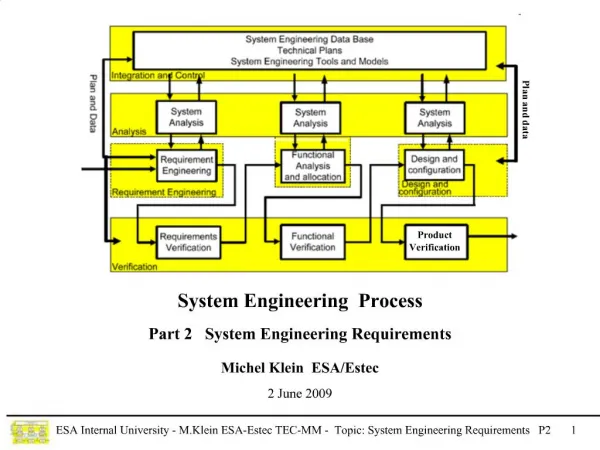
Systems EngineeringRequirements • Requirements flowed down to EFW via the Mission Requirements Document (MRD) • Includes references to the EFW Compliance Matrix, Environmental Spec, EME Spec, Contamination Control Spec, ICD, etc. • Includes Instrument Functional and Performance Requirements • An Instrument Requirements Document (RBSP_EFW_SYS_001) has been developed to flow these requirements down to the EFW subsystems • Requirements linked the MRD requirements • Requirements linked to the subsystem specifications • Subsystem specifications refer to their requirements from the IRD and how the design meets those requirements • Flight and SOC Software Requirements documents flow their requirements from the IRD down to the software modules • IRD specifies how each requirement is to be verified (Test, Analysis, etc) • EFW System Engineer has validated that the subsystem specifications describe an instrument that meets all the MRD requirements. EFW INST+SOC PDR
System EngineeringIRD Sample EFW INST+SOC PDR
System EngineeringVerification • Instrument Requirements Document (RBSP_EFW_SYS_001) identifies briefly how each requirement is verified • Verification, Validation, Test, and Calibration Plan (RBSP_EFW_TE_001) describes a plan for how requirements are verified • Discussed in I&T section • Requirements are verified as early as possible at a low level • Verifies subsystems, Retires risk • Requirements are verified at the highest level of assembly possible • Often involves verifying a requirement at several levels • System Engineer tracks Verification against IRD • Reports on status at PER, PSR EFW INST+SOC PDR
System EngineeringKey Performance Requirements EFW INST+SOC PDR
System EngineeringKey Subsystem Requirements EFW INST+SOC PDR
System EngineeringBlock Diagram EFW INST+SOC PDR
System EngineeringSubsystem Mechanical IDPU AXB (1 of 2), Stowed SPB (1 of 4), Stowed EFW INST+SOC PDR
System EngineeringBooms Deployed Axial Boom Deployment Unit (1 of 2) Four 40-50m Spin Plane Booms (SPB) Two 6m Axial Booms (AXB) Spin Plane Boom Deployment Unit (1 of 4) (IDPU Mounted Inside Bus) EFW INST+SOC PDR
System EngineeringICDs • Spacecraft to EFW ICD in preliminary stage (7417-9083) • Several iterations have closed out most issues • Sufficiently firm to support EFW design to start ETU build • EFW to EMFISIS ICD in preliminary stage (7417-9089) • Reached agreement on significant issues, working details • Sufficiently firm to support EFW design to start ETU build • MOC/SOC ICD in preliminary stage (7417-9050) • Several iterations have closed out most issues • EFW Subsystem specifications define interfaces between subsystems • IDPU Backplane specification – RBSP_EFW_BPL_001G • IDPU LVPS specification – RBSP_EFW_LVPS_001E • Axial Boom specification – RBSP_EFW_AXB_001- • Spin Plane Boom specification – RBSP_EFW_SPB_001- • Interconnect Drawings • RBSP_EFW_SYS_008C (harnessing) • RBSP_EFW_SYS_200A (pinouts) • RBSP_EFW_AXB_002G (AXB wiring schematic) • RBSP_EFW_SPB_002D (SPB wiring schematic) • RBSP_EFW_SYS_006 (Grounding) • RBSP_EFW_SYS_007A (IDPU Grounding) EFW INST+SOC PDR
System EngineeringFlight Software • Flight Software Development Plan documented in RBSP_EFW_FSW_001 • Flight Software Requirements documented in RBSP_EFW_FSW_002 • Major Requirements Include: • Spacecraft Interface Handling • Command Reception & Distribution • Real-Time Data Collection and Playback • On-Board Evaluation for Burst Triggering • Burst Data Collection and Playback • Boom Deployment Control • Details of flight software requirements and design discussed later EFW INST+SOC PDR
System EngineeringSOC Software • SOC Software Development Plan documented in RBSP_EFW_SW_001 • SOC Software Requirements documented in RBSP_EFW_SYS_010 • Major Requirements Include: • Command and Telemetry GSE (CTG): • Real time telemetry ingestion from MOC • Real time telemetry display, trending, and limit monitoring • Automated operator call-up on limit violation • Command Encoding and forwarding to MOC • Science Data Center (SDC): • Near-real time science displays • Off-line processing including Level 0 to Level 1,2 processing • Burst selection • Science Data Analysis • Details of SOC software requirements and design discussed in GSE and SOC sections EFW INST+SOC PDR
System EngineeringEnvironmental • EFW to survive all environments to be encountered during ground operations, launch, and on orbit • EFW to operate in spec over all environments to be encountered during ground functional tests, on-orbit commissioning and science phases • Science Performance not achieved until booms deployed (during commissioning) • RBSP Environmental Requirements called out in 7417-9019 • RBSP EME Requirements called out in 7417-9018 • EFW Verification Plan described in RBSP_EFW_TE_001 • Describes how EFW will verify compliance with requirements, including environmental requirements • Plan discussed in more detail in I&T section EFW INST+SOC PDR
System EngineeringEnvironmental Test Matrix EFW INST+SOC PDR
System EngineeringMechanical • Instrument designed to Environmental Specification Requirements: • Limit Loads, Stiffness, Venting, Shock • Mechanical Interfaces, Mass NTE called out in the ICD (7417-9083) • Instrument tested per Environmental Spec: • Mass Properties at component level • Mass, CG • MOI by analysis • Sine, Random vibration at component level • ETU to qualification levels • FM to acceptance levels • No acoustic test planned (no acoustically sensitive parts) • Mechanical Design and Analyses called out in Mechanical section EFW INST+SOC PDR
System EngineeringThermal REVISED • EFW interface temperature limits called out in the MRD and ICD • Operational: -25ºC to +55ºC • Survival: -30ºC to +60ºC • EFW components conductively coupled to spacecraft deck • EFW Thermal design verified by analysis and Thermal Vacuum testing • Analysis to include launch transients (heating) • Modeling and Analysis performed cooperatively between EFW and APL • Verification testing (Thermal Vac) described in I&T section • Thermal design and analysis described in the Thermal Design presentation. EFW INST+SOC PDR
System EngineeringEME (1) • Instrument conforms to Design Guidelines and Requirements in 7471-9019: • Magnetics • Identified magnetic materials and circuits are provided to Magnetics Working Group, which shall maintain a watch list and participate in analysis and suggestions for mitigations as required • Deployment motors contain permanent magnets, and shall be shielded • THEMIS test results indicate shielding is effective • Magnetics will be verified by magnetics screening at the component level (ETU and Flight) • ESC • Exterior surfaces are conductive and connected to chassis ground • Boom exterior connected via a resistor • ESC Verification at the component level • surface resistance measurements • Radiation • IDPU and preamp shielding to mitigate radiation environment • Parts selected for radiation tolerance as demonstrated by TID, SEE tests, verified by APL PCB EFW INST+SOC PDR
System EngineeringEME (2) • DDD • IDPU shielding to 350 mils, including connectors • Preamps have survived DDD testing • Spacecraft data interface uses APL-demonstrated DDD-insensitive parts • EFW boom unit interface DDD immunity by analysis (mostly capacitive protection) • EMFISIS interface DDD immunity by analysis and/or test (pending) • EMC: • IDPU box design includes EMC closeout (stair-step joints, vent shielding, connector close-out) • Harness has complete over-shield braid terminated on connector backshells • Supply frequency is above 400kHz, synchronized. • Supply has front end filtering, soft start • Verification by EMC tests: • ETU (CE) • FM1 (CE, CS, RE, RS, BI, On/Off transients) • FM2 (CE, BI) • Will partially deploy SPB to support Observatory EMC self-compatibility test EFW INST+SOC PDR
System EngineeringGrounding Diagram EFW INST+SOC PDR
System EngineeringMass Budget EFW INST+SOC PDR
System EngineeringPower Budget • 3 Power Services: • Operating Power (8.93W CBE, 0.92A Peak) • Spin Plane Boom Deployment Power (4A peak power, worst case) • Axial Boom Power (4A peak power worst case) EFW INST+SOC PDR
System EngineeringTelemetry Budget EFW INST+SOC PDR
System EngineeringCommanding • Real Time Instrument Command Requirements: • Configuring instrument at power-on (~50 commands) • Boom Deployment (up to 10 commands/minute during deployment) • Adjusting instrument periodically (~20 commands/month) • Burst Request (up to ~20 commands/day) • Rare Memory Load (<64kbytes) • Time-Tagged Command Requirements • Mode adjustments at different parts of the orbit (~20 commands/orbit) • Most commands are small (~10 bytes with header) • Except Memory Load commands EFW INST+SOC PDR
System EngineeringTechnical Changes since SRMDR EFW INST+SOC PDR
System EngineeringDesign Trades (1) Design Trades completed during Phase B EFW INST+SOC PDR
System EngineeringDesign Trades (2) Design Trades to be completed If not complete by MPDR, there will be additional cost/schedule impacts EFW INST+SOC PDR
This page intentionally almost blank EFW INST+SOC PDR