Download
1 / 26
270 likes | 464 Views
Unit 7 Multi-Level Gate Circuits / NAND and NOR Gates. Ku-Yaw Chang canseco@mail.dyu.edu.tw Assistant Professor, Department of Computer Science and Information Engineering Da-Yeh University. Objectives.

E N D
Unit 7Multi-Level Gate Circuits / NAND and NOR Gates Ku-Yaw Chang canseco@mail.dyu.edu.tw Assistant Professor, Department of Computer Science and Information Engineering Da-Yeh University
Objectives • Design a minimal two-level or multi-level circuit of AND and OR gates to realize a given function. • Design or analyze a two-level gate circuit using any one of the eight basic forms. • Design or analyze a multi-level NAND-gate or NOR-gate circuit. Fundamentals of Logic Design
Objectives • Convert circuits of AND and OR gates to circuits of NAND gates or NOR gates, and conversely, by adding or deleting inversion bubbles. • Design a minimal two-level, multiple-output AND-OR, OR-AND, NAND-NAND, or NAND-NOR circuit using Karnaugh maps. Fundamentals of Logic Design
Outline • 7.1 Multi-Level Gate Circuits • 7.2 NAND and NOR Gates • 7.3 Design of Two-Level Circuits Using NAND and NOR Gates • 7.4 Design of Multi-Level NAND and NOR Gate Circuits • 7.5 Circuit Conversion Using Alternative Gate Symbols • 7.6 Design of Two-Level, Multiple-Output Circuits • 7.7 Multiple-Output NAND and NOR Circuits Fundamentals of Logic Design
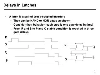
7.1 Multi-Level Gate Circuits • Level • Maximum number of gates cascaded in series between a circuit input and the output Fundamentals of Logic Design
Four-Level Realization of Z Fundamentals of Logic Design
Terminology • AND-OR circuit • A two-level circuit composed of a level of AND gates followed by an OR gate at the output Fundamentals of Logic Design
Terminology • OR-AND circuit • A two-level circuit composed of a level of OR gates followed by an AND gate at the output Fundamentals of Logic Design
Terminology • OR-AND-OR circuit • A three-level circuit composed of a level of OR gates followed by a level of AND gates followed by an OR gate at the output Fundamentals of Logic Design
Terminology • Circuit of AND and OR gates • No particular ordering of the gates • The output gate may be either AND or OR. Fundamentals of Logic Design
Trade-off • Number of • Gates • Gate inputs • Levels • Gate delay Fundamentals of Logic Design
Example 7-1 • Z = (AB+C) (D+E+FG) + H Fundamentals of Logic Design
Example 7-1 • Partially multiplying out Z = (AB+C) (D+E+FG) + H = (AB+C) [(D+E)+FG] + H = AB(D+E) + C(D+E) + ABFG + CFG + H Fundamentals of Logic Design
Example 7-1 Fundamentals of Logic Design
Example 7-1 Fundamentals of Logic Design
Problem • Find a circuit of AND and OR gates to realize f(a, b, c, d) = ∑ m(1, 5, 6, 10,13, 14) Fundamentals of Logic Design
Solution • First, simplify f by using a Karnaugh map f(a, b, c, d) =∑ m(1, 5, 6, 10,13, 14) Fundamentals of Logic Design
Solution • This leads directly to a two-level AND-OR gate circuit f = a’c’d + bc’d + bcd’ + acd’ Fundamentals of Logic Design
Solution • Factoring f = a’c’d + bc’d + bcd’ + acd’yields f = c’d (a’ + b) + cd’(a + b) Fundamentals of Logic Design
Solution • This leads directly to a three-level OR-AND-OR gate circuit f = c’d (a’ + b) + cd’(a + b) Fundamentals of Logic Design
Solution • Both solutions have an OR gate at the output • Sum of products • Using 1s on the Karnaugh map • How about having an AND gate at the output? • Product of sums • Using 0s on the Karnaugh map Fundamentals of Logic Design
Solution • Secondly, simplify f by using a Karnaugh map(considering 0s) f’ = c’d’ + ab’c’ + cd + a’b’cf = (c+d) (a’+b+c) (c’+d’) (a+b+c’) Fundamentals of Logic Design
Solution • This leads directly to a two-level OR-AND circuit f = (c+d)(a’+b+c)(c’+d’)(a+b+c’) Fundamentals of Logic Design
Solution • Partially multiplying out f = (c+d)(a’+b+c)(c’+d’)(a+b+c’)using (X+Y)(X+Z) = X+YZ f = [c + d(a’+b)] [c’ + d’(a+b)] = (c+a’d+bd)(c’+ad’+bd’) Fundamentals of Logic Design
Solution • This leads directly to a three-level AND-OR-AND circuit f = (c+a’d+bd)(c’+ad’+bd’) Fundamentals of Logic Design
Comparison Fundamentals of Logic Design