Performance Simulations of a Phase Stabilization System for CTF3 Kicker Phase Monitoring
This document presents the performance simulations of a phase stabilization system prototype designed for the CLIC Test Facility (CTF3). The focus is on a feed-forward correction scheme that aims to enhance the stability of the drive beam phase, crucial for the proper acceleration of the main beam. Through simulations, we analyze the correlations of phase measurements taken at different points in the system and propose a corrective approach utilizing a chicane of electromagnetic kickers. The results indicate a viable method for reducing phase errors, with significant implications for future experiments and performance enhancements.

Performance Simulations of a Phase Stabilization System for CTF3 Kicker Phase Monitoring
E N D
Presentation Transcript
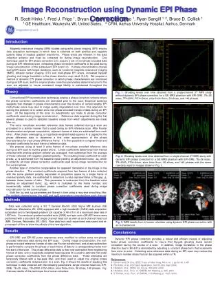
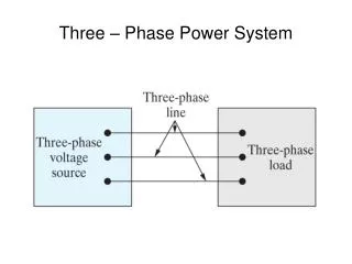
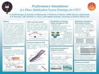
Performance Simulations of a Phase Stabilization System Prototype for CTF3 Kicker Phase monitor beam Combiner Ring Drive amplifier Signal Down-mixer A. Gerbershagen, D. Schulte, P. Skowronski, T. Persson, E. Ikarios, CERN, Geneva, SwitzerlandP. N. Burrows, G.B. Christian, C. Perry, John Adams Institute, University of Oxford, Oxford, UK • Performance simulation of feed-forward correction • In order to simulate the feed-forward we: • measure the phase at TL1 (10 ns steps); • Apply correction on the same train at TL2. • Figure of merit: • standard deviation • of the bunch phase. • Feed-forward is calculated with • b being the 20 ns corresponding to 50 MHz bandwidth. Average measured phase along • one train (in deg at 12 GHz) of TL1 (left) and TL2 (right) have a correlation of 0.85, and measure- • ments • have • different • standard • deviations. • Hence we • use a=1 and a=0.85×σ(TL2)/ σ(TL1) = 0.5. Also the limitation of the maximal correction (± 17° at 12 GHz) has been considered. Phase correction system Phase correction system is designed to reduce the bunch phase error at CLIC by a factor 10 before the drive beam decelerators. The system will send the beam in a chicane, varying the trajectory and time of flight of bunches in order to correct their phase. Scheme of the feed-forward chicane • Specification of correction system prototype for CTF3 • It is planned to install • a feedback system for the correction of the • mean phase of the trains and • the static errors within the trains; • a feed-forward system for the intra-train dynamic correction (scheme below). • The measurement will be performed at TL1 for feed-forwardsystem and at TL2 for feedback system, • the correction always applied at TL2. The amplifier is designed to have a ~50 MHz bandwidth for the 3 GHz beam at first stage. The electromagnetic kicker should provide a kick range of ± 1.2 kV and a maximal phase correction of ± 17° at 12 GHz. Abstract The CLIC drive beam provides RF power for acceleration of the main beam, and hence the drive beam’s longitudinal phase tolerances are very tight. A feedforward chicane consisting of four electromagnetic kickers is proposed as a correction system for the phase errors, which should allow loosening of the tolerances. A prototype of such a chicane system developed by CERN, INFN and the University of Oxford, is planned to be installed at CTF3 in 2012. The present poster summarizes the parameters of the planned phase correction system and presents simulations, which are used to make predictions of the performance of such a feedforward system at CTF3. Feedback processor Emittanceεx,y≤ 150μm Transverse jitter ≤ 0.3σ Current stability 0.75 x 10⁻³ Phase stability 0.2° @ 12GHz Bunch length stability 1% Electromagnetic kickers Feed-forward system folder options Phase monitor RF power stability 0.2% RF phase stability 0.05° Correction system for CTF3 CLIC Test Facility (CTF3) is a facility at CERN, constructed in order to test the central concepts of CLIC incl. the stabilization systems. Layout of CLIC Test Facility (CTF3) At CTF3 the correction system is planned to be integrated into the TL2 chicane, bending the trajectory as shown on the figure (right). Phase stability 2.5° @ 12GHz 0.2° @ 1GHz • Performance simulation of feedback correction • Measure train mean phase at TL2 • Correct this value on all bunches of the next train. • Figure of merit: standard deviation of train mean phase. Feedback is calculated with • With a=1 and a = correlation constant between two subsequent train means (0.61). Introduction CLIC is a linear e+e- collider based on the two-beam-scheme, in which the main beam is accelerated by the RF power extracted from the drive beam. The drive beam tolerances are very strict. Layout of the CLIC drive beam with the relevant tolerances and feed-forward system Summary and Outlook The simulations predict a measurable effect of phase correction system prototype at CTF3, allowing the experimental test of its functionality. The feed-forward correction range of ± 17° seems to be sufficient and hence the feedback system is optional.