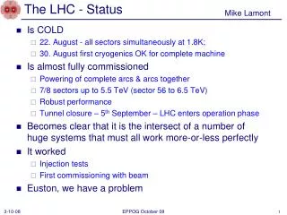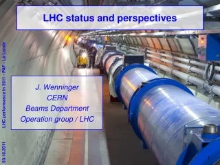
LHC Status
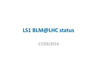
LHC Status. 12 October 2009 RRB Plenary R.-D. Heuer. 1. Repair of QRL service module in S3-4. After repair. Before repair. Q27. 4. Beam vacuum recovery in sector 3-4 Beam Vacuum Contamination. Role of the Enhanced QPS System. To protect against the new ‘problems’ discovered in 2008

LHC Status
E N D
Presentation Transcript
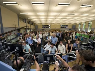
LHC Status 12 October 2009 RRB Plenary R.-D. Heuer 1
Repair of QRL service module in S3-4 After repair Before repair Q27 4
Role of the Enhanced QPS System To protect against the new ‘problems’ discovered in 2008 The Aperture-Symmetric Quench feature in the Main Dipoles and Defective Joints in the Main Bus-bars, inside or in-between the magnets. QPS Upgrade also allows precision measurements of the joint resistances at cold (sub-nΩ range) of every Busbar segment. This will allow complete mapping of the splice resistances (the bonding between the s.c. cables). To be used as the basic monitoring system for future determination of busbar resistances at warm (min. 80 K), to measure regularly the continuity of the copper stabilizers. Reminder 6
For installation in Phase 2 2 UPS Patch Panels / rack & 1 Trigger Patch Panel / rack total 3456 panel boxes The nQPS project DQQTE board for ground voltage detection (total 1308 boards, 3 units/crate) DQAMG-type S controller board 1 unit / crate, total 436 units DQLPUS Power Packs 2 units / rack (total 872 units) DQQBS board for busbar splice detection 5 such boards / crate, total 2180 units DQLPU-type S crate total 436 units DQQDS board for SymQ detection 4 boards / crate, total 1744 water cover ‘Internal’ and ‘external’ cables for sensing, trigger, interlock, UPS power, uFIP (10’400 + 4’400) Original racks 7
Good interconnect normal operation (1.9K) Magnet Magnet copper bus bar 280 mm2 copper bus bar 280 mm2 superconducting cable current interconnection (soldered) We must be sure that the joint between the sc cables is good. Measurements of nano-Ohms at 1.9K 9
good interconnect, after quench (>10K) Magnet Magnet copper bus bar 280 mm2 copper bus bar 280 mm2 Non superconducting cable interconnection Safe! Copper bus takes the current during the current decay following the quench 10
Bad interconnect, normal operation 1.9K Magnet Magnet copper bus bar 280 mm2 copper bus bar 280 mm2 superconducting cable interconnection No problem while the sc cable remains superconducting 11
Bad interconnect, after quench Current path is deviated through the sc cable (which is no longer sc). Depending on the current and length of this path, the cable can suffer thermal runaway Magnet Magnet copper bus bar 280 mm2 copper bus bar 280 mm2 Non-superconducting cable interconnection Danger of melting the sc cable then electrical arc We must be ensure that the copper stabiliser is continuous Measurements of micro-Ohms at warm SPC June 15, 2009 12
QEBI.11L4-M1-cryoline-lyra QEBI.11L4-M1-cryoline-connection Sector 3-4 : QEBI.11L4-M1-cryoline before repair QEBI.11L4-M1-cryoline connection (9.8 μΩ) lyra (51 μΩ) C. Scheuerlein TE-MSC 13
Total splice (16 cm) 19.6 μΩ QEBI.11L4-M1-cryoline connection 10.0 μΩ lyra 12.0 μΩ Sector 3-4 : QEBI.11L4-M1-cryoline repaired 14 C. Scheuerlein TE-MSC 14
Number of splices in RB, RQ circuits Mike Koratzinos
Non invasive splice resistance measurements • Summary of measurements performed on RB and RQ circuits • Huge effort of dedicated measurement teams • About 35000 manual measurements • Over 400 kilometers walked in the tunnel
R-measurement at 300 K 120 mm wedge bus bus U-profile 150 mm V V 160 mm I I 170 mm The “R16 method” will give some indication whether wedge, U-profile, and bus stabilizer are in good electrical contact. ‘Perfect’ values for R16 are: (T=18 C, gap is 0.1 mm fully filled with SnAg, perfect bonding everywhere, uniform current) RB: 9.45 mW RQ: 16.0 mW Due to point-like current insertion the measured resistances are about 1 mW higher. 17 A. Verweij, TE-MPE. 28 April 2009, TE-TM meeting
Decisionon Initial Beam Operating Energy(August 2009) • Highest measured value of excess resistance (Rlong) in 5 sectors measured at 300K was 53. • Operating at 7 TeV cm with energy extraction times of 50s, 10s (dipoles and quadrupoles) • Simulations show that resistances of 120are safe from thermal runaway under conservative assumed conditions of worst case conditions for the copper quality (RRR) and no cooling to the copper stabilizer from the gaseous helium. • Operating at 10 TeV cm with a dipole energy extraction time of 68 s • Simulations show that resistances of 67are safe from thermal runaway under conservative assumed conditions of worst case conditions for the copper quality (RRR), and with estimated cooling to the stabilizer from the gaseous helium. • Decision: Operation initially at 7 TeV cm (energy extraction time of 50s, 10s) with a safety factor or more than 2 for the worst stabilizers. During this time • monitor carefully all quenches to gain additional information. • Continue simulations and validation of simulations by experimentation (FRESCA) • Then operate at around 10 TeV cm.
S12 From Zinur’s Labview tool First Dipole Busbar Resistances from first scan to 2 kA
Since August 2009 • Start of re-establishment of spares situation as it was before the incident. • Helium leak (flexible in the DFBs) in S45, S23, and S81. All repaired. • Super-insulation fire in S67 (minimum damage). • Magnet/bus-bar short to earth in S67 (detected and repaired).
Cooldown status 12.10.2009
- 7 Sectors at operating temperature - 2 Sectors splice resistances measured Injection lines tested up to LHC for protons and ions First injection mid November Followed by collisions at injection energy Collisions at 7 TeV Towards 10 TeV in the course of 2010 Heavy Ion collisions at the end of the run in 2010 Big thank you to everybody helping 25