Download
1 / 23
230 likes | 261 Views
This document outlines the requirements and results of testing mirror support forces for optimal performance in telescope design. It includes analysis, errors, and strategies for achieving stability and precision in mirror positioning.

E N D
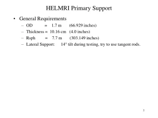
HELMRI Primary Support • General Requirements • OD = 1.7 m (66.929 inches) • Thickness = 10.16 cm (4.0 inches) • Rsph = 7.7 m (303.149 inches) • Lateral Support: 14° tilt during testing, try to use tangent rods.
Axial Support, Starting Point … Nelson 36 point • Nelson predicts 6.54 nm-rms with 36 support points Uniform Support forces are preferable Use three rings, round off angles
Nelson 36 point support, simplified somewhat 60° sector model used for optimizing actuator locations (with uniform support forces).
Initial Deformation (Simplified Nelson Support) • 7.87 nm-rms
FEM results, all support forces identical • Results of row positioning iterations: • FEM results use 120% of glass density • 5.84/1.2 = 4.87 nm-rms compared to 4.58 nm-rms Nelson optimized value.
Full Mirror Model • Full model is based on case 4 • Slightly more rms distortion than cases 5 or 6 but less power.
Full Mirror Analysis Results • 1 g Z, Surface is 5.88 nm-rms
1 g Lateral on 3 tangent rods • 1 g lateral load, 219 nm-rms (would be 53 nm-rms at 14°)
1 g lateral on strap (uniform radial support force) • 1 g gives 47 nm-rms surface (14° tilt gives 11.4 nm-rms) Supported edge Gravity vector
Net Performance • Mirror support force errors. • Actuator error force magnitudes: • Pneumatic rolling diaphragm MMT f/5 axial units (passive): • Fr, Ft ~ 0.007*Fax = 0.31 lbs • Fax ~ 0.27 Lbs • Mr, Mt ~ 0.016*Fax = 0.71 in-lbs • Mz ~ 0.8 in-lbs • Active actuators (closed loop on figure optional) can reduce axial error force to 0.07 Lbs or less. • Random error effects (random distribution) shown on next slide. • Systematic and low order effects are probably worse: • Systematic force distributions can be caused by: • Cell deflection (print through) • Temperature change • Friction and movement. • Low order effects: • Probability of random forces having a significant astigmatic or other low order component is quite good.
Random Error Force Effects, Preliminary Lateral on tangent rods not included Axial force errors are the major contributors
Effect of using a force loop to control axial force Lateral on tangent rods not included Axial force errors have been reduced to 0.07 Lbs
Customer Support Arrangement • 1 g z uniform support forces, 6.4 nm-rms surface
Customer Support Arrangement • 1 g z optimized axial support forces, 3.8 nm-rms surface
1 g Z (Z is normal to C/L of mirror) • Optimized Support Forces • Customer geometry • Zenith Pointing • Mirror weight = 1590.44 Lbs
1 g Lateral Loading, Optimized Fr, Ft at 6 Locations • Surface figure = 9.56 nm-rms, 0.256 P-V
Preliminary Performance Evaluation, Telescope • Optimized support forces including Fr and Ft at Six OD Locations
Optimized Forces, Lateral Loading, 9.56 nm-rms • Forces at constrained nodes must be derived from equilibrium considerations
Add Axial Force at Tangent Pads • 1 g Y, Surface = 3.7 nm-rms, 0.14 P-V
Optimized Reaction Forces, Lateral with Fz at Tangent Pads on OD • Green blocks are forces at constrained DOF’s obtained by summing • Need to confirm these values to verify equilibrium (not done)
Plan view of optimized lateral forces, 1 g Y Deviations from radial are expected based on Swesinger’s solution for meniscus mirrors.