Download
1 / 60
610 likes | 622 Views
This document outlines the discussion from a collaboration meeting on cooling shell design, covering thermal and fluid mechanics calculations, 3D design, simulations, and future tasks. The aim is to meet cooling requirements, work at -25°C, and ensure a leakless system. The process involves calculation, design, simulation, and testing. Detailed calculations include thermal sources, heat flow, power requirements, mass flow, and fluid mechanics for the outer shell parts. Simulations using Autodesk software assess thermal properties and fluid dynamics of the design components. The document concludes with a summary and outlines future tasks for the project.

E N D
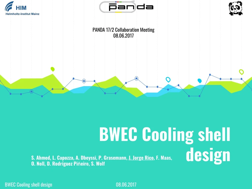
PANDA 17/2 Collaboration Meeting 08.06.2017 BWEC Cooling shell design S. Ahmed, L. Capozza, A. Dbeyssi, P. Grasemann, J. Jorge Rico, F. Maas, O. Noll, D. Rodríguez Piñeiro, S. Wolf BWEC Coolingshell design 08.06.2017
Contents • Overview • Calculations (thermal and fluid mechanics) • 3D design • Simulations (thermal and fluid mechanics) • Summary and future tasks 2 BWEC Coolingshell design 08.06.2017
Overview 1 What is our aim? 3 BWEC Coolingshell design 08.06.2017
Overview • Overview • Cooling requirements • Work at -25°C • Maximum 500 mbar pressure drop (leakless-mode) • Limited space • Low temperature gradient Outer shell Inserts Mounting plate Cover Front cooling Boards Vacuum insulation panel (VIP) Crystals Coolant Inner shell 4 BWEC Coolingshell design 08.06.2017
THE PROCESS IS THIS Calculate & Design Simulate Test 5 BWEC Coolingshell design 08.06.2017
Calculations 2 Thermal and fluid mechanics calculations of the cooling shells 6 BWEC Coolingshell design 08.06.2017
Thermal calculations Heat sources • Electronics • Heat flow through the walls • Power to cool down P +70C ° ° • APFEL 1.5 7 BWEC Coolingshell design 08.06.2017
Thermal calculations Electronics • 150 mW/crystal * 524 crystals =78.60 W • Applied in back side of crystals • Cables out of the detector are not taken into account 8 BWEC Coolingshell design 08.06.2017
Outer face Thermal calculations Heat flow through walls Front face Back face Worst case at 70°C surrounding temperature Inner face 9 BWEC Coolingshell design 08.06.2017
Thermal calculations Power to cool down • Constant cooling flow • Initial temperature 30°C • Final temperature -25°C • Time 24 h 10 BWEC Coolingshell design 08.06.2017
Summary of heat sources Safety factor 1.5 11 BWEC Coolingshell design 08.06.2017
Thermal calculations Mass flow calculation • 0.3 °C between inlet and outlet (homogeneity) • 2 outer shells and 2 inner shells • Outer shell 7.34 l/min • Inner shell 3.10 l/min Distance between pipes • 0.25 °C max temperature difference (homogeneity) • 15 mm thickness • L= 150 mm L 12 BWEC Coolingshell design 08.06.2017
Fluid mechanics calculations(Half outer shell) Outer shell parts • 6 pipes d = 13 mm • 4 pipes d = 10 mm • 5 front square connectors • 4 back elbow connectors 13 BWEC Coolingshell design 08.06.2017
Fluid mechanics calculations Pipe with d = 10 mm Elbow of d = 10 mm Square connector (estimation) Pipe with d = 13 mm 14 BWEC Coolingshell design 08.06.2017
Fluid mechanics calculations summary 15 BWEC Coolingshell design 08.06.2017
🎨 3D design 3 An overview of the outer shell 3D design 16 BWEC Coolingshell design 08.06.2017
3D design 17 BWEC Coolingshell design 08.06.2017
3D design • Front square connectors • Back elbows 18 BWEC Coolingshell design 08.06.2017
Simulations 4 Thermal and fluid mechanics simulations Autodesk Simulation Mechanical & Autodesk CFD 2016 19 BWEC Coolingshell design 08.06.2017
Thermal simulations Outer shell(Aluminum) 1 quarter dummy for simulations Front shell(HDPE) Inserts(Aluminum) Gap(air 4mm) Crystals(PbWO4) Inner shell(Aluminum) 20 BWEC Coolingshell design 08.06.2017
Thermal simulations Only outer and inner shells • Not front shielding • 2°C gradient -25.08 °C -23.14 °C 21 BWEC Coolingshell design 08.06.2017
Thermal simulations Back pipe with both inner and outer shells • Back homogeneity -25.10 °C • Not front shielding • 2°C gradient -23.16 °C 22 BWEC Coolingshell design 08.06.2017
Thermal simulations Front shell, back pipe and both inner and outer shells Out of scale -5°C • Front shielding • Less than 0.5°C gradient -25.00 °C • Solid angle loss (further for the IP) -24.00 °C 23 BWEC Coolingshell design 08.06.2017
Thermal simulations Possible 140W (STT worst elect. case) front without front cooling -25,06 °C • Huge temperature gradient (7.13°C) -17.87°C 24 BWEC Coolingshell design 08.06.2017
Thermal simulations Possible 140W (STT worst elect. case) front with front cooling Out of scale 57°C • Good front protection • Less than 0.5°C gradient -25.00 °C • Solid angle loss (further from the IP) -24.00°C 25 BWEC Coolingshell design 08.06.2017
Fluid mechanics simulations Straight pipesandelbow 4.00 mbar 23.82 mbar 11.63 mbar 26 BWEC Coolingshell design 08.06.2017
Fluid mechanics simulations Front square connectors 27 BWEC Coolingshell design 08.06.2017
Fluid mechanics simulations Front square connectors 28 BWEC Coolingshell design 08.06.2017
Fluid mechanics simulations Front square connectors 29 BWEC Coolingshell design 08.06.2017
Fluid mechanics simulations Front square connectors 35.44 mbar 31.21 mbar 30.28 mbar 30 BWEC Coolingshell design 08.06.2017
Fluid mechanics simulations Summary 31 BWEC Coolingshell design 08.06.2017
Fluid mechanics calculations vs. simulations 32 BWEC Coolingshell design 08.06.2017
Summary and future works 5 What is next? 33 BWEC Coolingshell design 08.06.2017
Summary • Less than 0.3oC of gradient in the coolant temperature • Good homogeneity with front cooling • Low pressure drop: • Different pressure drop values because of the square parts (simplifications in calculations for complex geometry) 34 BWEC Coolingshell design 08.06.2017
Future works Building an outershell prototype (on process) Make measurements for validating calculations and simulations Tests for front cooling with existing prototype (on process) Design inner shell with the same procedure 35 BWEC Coolingshell design 08.06.2017
THANKS! Any questions? You can write me jjorgeri@uni-mainz.de 36 BWEC Coolingshell design 08.06.2017
Back Up slides 08.06.2017 BWEC Coolingshell design
Front cooling Preparation in Outer shell and MP Connectors MP Hole B1 BWEC Coolingshell design 08.06.2017
Front cooling Preliminary design • Parallel circuits (low pressure drop) • Different diameter each branch (homogeneity) • 3D printed (HDPE) B2 BWEC Coolingshell design 08.06.2017
Simulations Velocity examples B3 BWEC Coolingshell design 08.06.2017
Thermal calculations General inputs B4 BWEC Coolingshell design 08.06.2017
Thermal calculations Example B5 BWEC Coolingshell design 08.06.2017
Thermal calculations Output summary B6 BWEC Coolingshell design 08.06.2017
Fluid mechanic calculations Serial Pressure drop calculator • Inputs: • Coolant • Section´s geometry • Length • Local elements • Flow • Valve • Height B7 BWEC Coolingshell design 08.06.2017
Fluid mechanic calculations Serial Pressure drop calculator • Outputs: • Reynolds • Laminar/ Turbulent • Friction factor • Pressure drop • Pressure difference B8 BWEC Coolingshell design 08.06.2017
Fluid mechanic calculations Parallel calculator Flow • Aim: • Constant flow through • all branches. • Procedure: • Change diameter of branches. Flow/4 Flow/4 Flow/4 Flow/4 Flow B9 BWEC Coolingshell design 08.06.2017
Fluid mechanic calculations Parallel calculator • Inputs: • Coolant • Different geometry for sections • Lengths • Local elements • Number of branches • Height • . B10 BWEC Coolingshell design 08.06.2017
Fluid mechanic calculations Parallel calculator • Outputs: • Total pressure drop • Pressure drop in manifold • Different diameters • . B11 BWEC Coolingshell design 08.06.2017
Front cooling test Different materials • Aim: • See the effect of different materials • in the front cooling • Effect of different VIP´s configuration • 20mm • 2x10mm • Validate thermal and fluid mechanic • calculation system. • . B12 BWEC Coolingshell design 08.06.2017
Front cooling test Different materials • Layout • . B13 BWEC Coolingshell design 08.06.2017