1996 Buick Skylark Service Repair Manual
0 likes | 18 Views
To get the complete manual, please open the home page website.<br><br>https://www.aservicemanualpdf.com/<br>

1996 Buick Skylark Service Repair Manual
E N D
Presentation Transcript
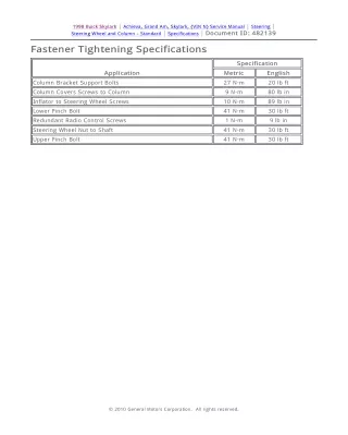
Document ID: 482139 Page 1 of 1 1998 Buick Skylark | Achieva, Grand Am, Skylark, (VIN N) Service Manual | Steering | Steering Wheel and Column - Standard | Specifications | Document I D: 482139 Fastener Tightening S pecifications Specification Application Metric English Column Bracket Support Bolts 27 N·m 20 lb ft Column Covers Screws to Column 9 N·m 80 lb in Inflator to Steering Wheel Screws 10 N·m 89 lb in Lower Pinch Bolt 41 N·m 30 lb ft Redundant Radio Control Screws 1 N·m 9 lb in Steering Wheel Nut to Shaft 41 N·m 30 lb ft Upper Pinch Bolt 41 N·m 30 lb ft © 2010 General Motors Corporation. All rights reserved. http://localhost:9001/si/showDoc.do?docSyskey=482139&pubCellSyskey=58585&pubO... 10/14/2010
Document ID: 609365 Page 1 of 2 1998 Buick Skylark | Achieva, Grand Am, Skylark, (VIN N) Service Manual | Steering | Steering Wheel and Column - Standard | Visual Identification | Document I D: 609365 Steering Column Disassembled V iew Standard Steering Column (1) Flanged Prevailing Torque Nut (2) Retaining Ring (3) SIR Coil (4) Wave Washer (5) Bearing Retainer (6) Shaft Lock (7) Turn Signal Cancel Cam Assembly (8) Upper Bearing Spring (9) Upper Bearing Inner Race (10) Adapter Screws © 2010 General Motors Corporation. All rights reserved. http://localhost:9001/si/showDoc.do?docSyskey=609365&pubCellSyskey=58699&pubO... 10/14/2010
Document ID: 609365 Page 2 of 2 (11) Steering Column Housing Assembly (12) Ignition Lock Actuator Assembly (13) Lock Pre-Load Spring (14) Ground Strap (15) Mounting Plate (16) Bearing Retainer (17) Ignition Switch Assembly (18) Tapping Screws (19) Lock Bolt Assembly (20) Lock Bolt Support Bracket (21) Tapping Screws (22) Bearing Retainer (23) Steering Shaft Assembly (24) Support Screws (25) Support Mounting Adapter (26) Steering Column Jacket Assembly (27) Wire Restraint Clip (28) Adapter and Bearing Assembly (29) Lower Bearing Seat (30) Lower Bearing Spring (31) Lower Spring Retainer http://localhost:9001/si/showDoc.do?docSyskey=609365&pubCellSyskey=58699&pubO... 10/14/2010
Document ID: 540047 Page 1 of 7 1998 Buick Skylark | Achieva, Grand Am, Skylark, (VIN N) Service Manual | Steering | Steering Wheel and Column - Standard | Component Locator | Document I D: 540047 Standard W heel/ Column Component View s Center Console (1) PRNDL Connector (2) ETS Connector (3) Automatic Transaxle Control (4) Clip LH Low er I nstrument Panel near Steering Column © 2010 General Motors Corporation. All rights reserved. http://localhost:9001/si/showDoc.do?docSyskey=540047&pubCellSyskey=58683&pubO... 10/14/2010
https://www.aservicemanualpdf.com/ My Dear Friend! Thank you very much for visiting. Full manual if required, please enter the following URL into your browser. https://www.aservicemanualpdf.com/
Document ID: 540047 Page 2 of 7 (1) Cruise Control Brake Switch (2) Brake Switch (3) SIR Branch (4) SIR SDM Harness (5) Cruise Control Switch Center I nstrument Panel near Tie Bar http://localhost:9001/si/showDoc.do?docSyskey=540047&pubCellSyskey=58683&pubO... 10/14/2010
Document ID: 540047 Page 3 of 7 (1) S227 (2) S439 (3) S391 (4) ETS (5) BTSI (6) PRNDL Control Module (7) S277 (8) S327 LH S ide of the Engine Compartment http://localhost:9001/si/showDoc.do?docSyskey=540047&pubCellSyskey=58683&pubO... 10/14/2010
Document ID: 540047 Page 4 of 7 (1) Engine Compartment Fuse Center (2) Fuse Block Bracket (3) Battery LH S ide of I nstrument Panel http://localhost:9001/si/showDoc.do?docSyskey=540047&pubCellSyskey=58683&pubO... 10/14/2010
Document ID: 540047 Page 5 of 7 (1) Steering Column Wiring Branch (2) DLC Cover (3) Screw (4) DLC (5) Rear Defogger Relay (6) Fuse Block Low er LH of Steering Column http://localhost:9001/si/showDoc.do?docSyskey=540047&pubCellSyskey=58683&pubO... 10/14/2010
Document ID: 540047 Page 6 of 7 (1) Multi-Function Lever (2) SIR Coil (3) Ignition Lock Solenoid (4) Passlock Connector Lead (5) Windshield Wiper Switch Lead (6) SIR Lead (7) SIR Connector (8) DLC Lead (9) S128 (10) S127 (11) S200 (12) S205 (13) S204 (14) S423, S424 (15) LH Stalk Switch Branch (16) S202 (17) Headlamp Switch Lead (18) Ignition Switch Connector (19) Wiper Switch (20) Passlock Connector Lead LH S ide of Engine http://localhost:9001/si/showDoc.do?docSyskey=540047&pubCellSyskey=58683&pubO... 10/14/2010
Document ID: 540047 Page 7 of 7 (1) Ground Lead (2) Transaxle Range Switch (3) Trans Shift Cable Bracket (4) Engine Wiring Harness (4) Engine Wiring Harness (5) Engine Harness To Rear Lead (6) S111, A/C Diode, S110 (7) Coolant Fan (8) Automatic Transaxle Connector http://localhost:9001/si/showDoc.do?docSyskey=540047&pubCellSyskey=58683&pubO... 10/14/2010
Document ID: 541096 Page 1 of 1 1998 Buick Skylark | Achieva, Grand Am, Skylark, (VIN N) Service Manual | Steering | Steering Wheel and Column - Standard | Component Locator | Document I D: 541096 Standard W heel/ Column Connector End V iew s Transaxle Range Sw itch C1 • 12191757 Connector Part I nformation • 4-W ay F Metri-Pack Series 150 ( LT GRY ) Pin W ire Color Circuit No. Function A WHT 776 Transaxle Position Switch Signal - Parity BIT B YEL 772 Transaxle Position Switch Signal - BIT 2 C GRY 773 Transaxle Position Switch Signal - BIT 3 D BLK/WHT 771 Transaxle Position Switch Signal - BIT 1 © 2010 General Motors Corporation. All rights reserved. http://localhost:9001/si/showDoc.do?docSyskey=541096&pubCellSyskey=58684&pubO... 10/14/2010
Document ID: 482224 Page 1 of 3 1998 Buick Skylark | Achieva, Grand Am, Skylark, (VIN N) Service Manual | Steering | Steering Wheel and Column - Standard | Repair Instructions | Document I D: 482224 I gnition Lock Cylinder Replacement - On V ehicle ( W ith Key) Removal Procedure Caution: Unless directed otherwise, the ignition and start switch must be in the OFF or LOCK position, and all electrical loads must be OFF before servicing any electrical component. Disconnect the negative battery cable to prevent an electrical spark should a tool or equipment come in contact with an exposed electrical terminal. Failure to follow these precautions may result in personal injury and/or damage to the vehicle or its components. 1. 2. Disconnect the negative battery cable. Disable the supplemental inflatable restraint (SIR) system. Refer to Disabling the SIR System in SIR. Remove the three screws from the lower left insulator panel. Remove the lower left insulator panel. Disconnect 2 yellow 2-way SIR connectors. Remove the tilt lever. Refer to Tilt Lever Replacement - On Vehicle in Steering Wheel and Column - Tilt. 3. 4. 5. 6. 7. Remove 3 Torx® screws (4) from the trim covers. (Pontiac and Oldsmobile shown, Buick similar) Remove the upper steering column trim cover (1). Remove the lower steering column trim cover (5). 8. 9. © 2010 General Motors Corporation. All rights reserved. http://localhost:9001/si/showDoc.do?docSyskey=482224&pubCellSyskey=58677&pubO... 10/14/2010
Document ID: 482224 Page 2 of 3 10. 11. Turn the ignition lock cylinder (6) to the RUN position. Push down and hold the ignition lock cylinder locking button on the rear of the bearing and housing assembly. Remove the ignition lock cylinder by pulling the ignition lock cylinder (6) away from the steering column. 12. Installation Procedure 1. Install the ignition lock cylinder (6) into the steering column: 1.1. Turn the lock cylinder to the RUN position. 1.2. Push in the lock cylinder while rotating the key approximately 5 degrees in the http://localhost:9001/si/showDoc.do?docSyskey=482224&pubCellSyskey=58677&pubO... 10/14/2010
Document ID: 482224 Page 3 of 3 counterclockwise direction. 2. Install the upper steering column cover (1) and the lower steering column cover (5) with 3 Torx® head screws (4). Install the tilt lever. Refer to Tilt Lever Replacement - On Vehicle in Steering Wheel and Column - Tilt. Connect 2 yellow 2-way SIR connections. Install the lower left insulator panel with 3 screws. Enable the SIR system. Refer to Enabling the SIR System in SIR. Connect the negative battery cable. Perform the Passlock Learn Procedure. Refer to Vehicle Theft Deterrent (VTD) Operation in Theft Deterrent. 3. 4. 5. 6. 7. 8. http://localhost:9001/si/showDoc.do?docSyskey=482224&pubCellSyskey=58677&pubO... 10/14/2010
Thank you very much for your reading. Please Click Here Then Get Information. More
https://www.aservicemanualpdf.com/ My Dear Friend! Thank you very much for visiting. Full manual if required, please enter the following URL into your browser. https://www.aservicemanualpdf.com/