ELECTRICAL CURRENT
A voltage divider circuit or potentiometer circuit is used to continuously change the voltage that is applied to a consumer (incandescent lamp, motor, ...). With the change in voltage, you can e.g. B. regulate the brightness of an incandescent lamp or the speed of a motor continuously.<br><br>A resistor with three connections, which is also known as a potentiometer, is used to divide the voltage. It can be viewed as a series connection of two partial resistors. According to the voltage divider rule, the applied partial voltages behave like partial resistances.

ELECTRICAL CURRENT
E N D
Presentation Transcript
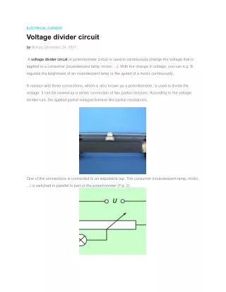
ELECTRICAL CURRENT Voltage divider circuit by Burraq December 24, 2021 A voltage divider circuit or potentiometer circuit is used to continuously change the voltage that is applied to a consumer (incandescent lamp, motor, ...). With the change in voltage, you can e.g. B. regulate the brightness of an incandescent lamp or the speed of a motor continuously. A resistor with three connections, which is also known as a potentiometer, is used to divide the voltage. It can be viewed as a series connection of two partial resistors. According to the voltage divider rule, the applied partial voltages behave like partial resistances. One of the connections is connected to an adjustable tap. The consumer (incandescent lamp, motor, ...) is switched in parallel to part of the potentiometer (Fig. 2).
In simplified terms, the potentiometer can be viewed as a series connection of two resistors (Fig. 3). How big the partial resistances R1another R2 depends on the position of the tap. If two resistors are connected in series, the following applies: I1=I2 If the quotient of voltage and current is used for the current intensity, one obtains: U1/R1=U2/R2 or U1/U2=R1/R2 This law is called the voltage divider rule. This voltage divider rule results in the potentiometer circuit: The greater partial voltage is at the larger partial resistance. If a device is connected in parallel to the partial resistance, the same voltage is applied to the consumer as to the relevant partial resistance, because for a parallel connection of resistors, the voltage across the two parallel-connected resistors is the same. All of the above considerations apply to an unloaded potentiometer. One speaks of this when the resistance of the consumer is very high, eg B. only one voltmeter is switched on as shown in Figure 3. Does the consumer have any resistance Ra, a current also flows through this resistor. The resistors connected in parallel R1other Ra are connected in series with the resistor R2 (Picture 4). If you
apply the laws in circuits to this parallel and series connection, you get for the voltage at the consumer : U1=U⋅R1/(R1+R2+(R1⋅R2)/Ra) Tags:Electrical currentelectruical voltageVoltage divider circuit