Download
1 / 17
170 likes | 289 Views
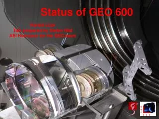
Dual Recycling for GEO 600. Andreas Freise , Hartmut Grote Institut für Atom- und Molekülphysik Universität Hannover Max-Planck-Institut für Gravitationsphysik 27. March 2003. Dual Recycling Concept.

E N D
Dual Recycling for GEO 600 Andreas Freise, Hartmut Grote Institut für Atom- und Molekülphysik Universität Hannover Max-Planck-Institut für Gravitationsphysik 27. March 2003
Dual Recycling Concept • two recycling cavities enhance independently the carrier light and the signal sidebands • shot noise limited sensitivity is improved (typically by a factor of 102 to 103) MPR MSR
final optics 300 W at Beam Splitter test optics 2 W 1 W ~ 10 mW GEOStatus March 2003 Michelson Interferometer Mode Cleaners Laser MPR MSR
Common arm length: • (laser frequency stabilsation) • Pound-Drever-Hall to laser frequency Dual Recycling Control Mode Cleaners 37.2 MHz 14.9 MHz 9 MHz • Differential arm length: • (gravitational wave signal) • heterodyne detection • Schnupp modulation Laser • Signal-Recycling control: • a separate modulation frequency • reflected beam from AR coating
Power Recycling End mirrors with imperfect radius of curvature beamsplitter: „tilt“ motion
MI MPR MSR From Power- to Dual Recycling Optical signals change because control sidebands and higher order TEM modes experience a coupled, 4-mirror cavity. Transfer function for control sidebands must be maximised for various possible configurations: • MI arm length difference: 10 cm • cavity length difference: 9 cm
with signal recycling: ModeHealing Each recycling cavity minimises the loss due to mode mismatch of the respective other power recycling only:
MSR with T=1% yields almost perfect mode healing Mode Healing Mode healing Mirror curvature compensation
Control Sidebands (SR) Resonance condition in the detuned, coupled, 4-mirror cavity: fSR= 72 ·FSRSRC 9MHz Detuning the modulation frequency and/or the demodulation phase changes the SR operating point
SRC Error Signal Example operating point for 200 Hz detuning
SRC Error Signal Largely detuned operating point for lock acquisition
Nominal operating points Lock acquisition operating points MI Error Signal Normalisation
Lock Acquisition Dark fringe power Intra cavity power MI error point MI fast feedback MI slow feedback SR error point SR feedback
Next Steps ramp MI gain to make system more robust PR + MI locked simulatnious ramping of SR modulation frequency and demodulationphase to search for SR fringe computer controlled lock acquisition of the autoalignment systems