Download
1 / 33
380 likes | 715 Views
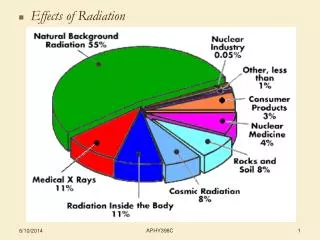
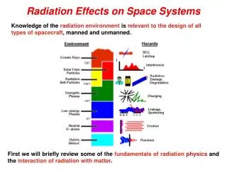
Radiation Effects on Space Systems. Knowledge of the radiation environment is relevant to the design of all types of spacecraft , manned and unmanned. First we will briefly review some of the fundamentals of radiation physics and the interaction of radiation with matter.

E N D
Radiation Effects on Space Systems Knowledge of the radiation environment is relevant to the design of all types of spacecraft, manned and unmanned. First we will briefly review some of the fundamentals of radiation physics and the interaction of radiation with matter.
ASEN-5335 Aerospace Environments -- Radiation Effects on Space Systems Monte Carlo techniques are often used to estimate gross effects of the cascade process. In the simplest models, analytical/empirical expressions are fit to these results or actual measurements to give estimates of the end products produced as a function of depth in the shielding material. Radiation and Spacecraft Design There are 3 primary considerations in the design of spacecraft for radiation effects: Specification/prediction of the radiation environment, and its variability Determination of how that radiation propagates through material to the target area (Note: this involves generation of many secondary particles.) Knowing how radiation at the target affects specific spacecraft components (circuitry, solar cells, etc.) From the standpoint of radiation interactions with matter, 3 types of radiation need to be considered: Photons (primarily EUV, X-rays, & gamma rays) Charged particles (protons, electrons & heavy ions) Neutrons -- produced as secondary particles as GCRs interact with Aluminum Principal physical characteristics of interest: Impacting Particles: mass, charge and K.E. Target Material: mass and density
ASEN-5335 Aerospace Environments -- Radiation Effects on Space Systems If the electron moves too fast, it "passes through" without effectively interacting with the ambient atoms and molecules. If the electron is moving too slowly, it lacks the K.E. necessary to create ionizations. BASIC RADIATION PHYSICS As an example of the interaction between radiation and matter, an energetic electron passing through air will leave a trail of ionized particles: Consequently, radiation damage to materials is dependent not only on the nature of the radiation, but on the energy of the radiation and the nature of the material itself.
ASEN-5335 Aerospace Environments -- Radiation Effects on Space Systems Photoelectric Effect Photon completely absorbed by the emitted L-(outer) shell or K-shell electron Pair Production Photons with sufficiently high energies are fully absorbed by a sufficiently high-Z material. A positron-electron pair is then formed Compton Scattering The incident is so energetic that it is not completely absorbed. Part of the energy goes into scattering an electron (“Compton electron”), and the rest into a scattered lower-energy photon. Photon Interactions Note: The products of these interactions further interact with the target material, producing a complex cascade of electrons and photons.
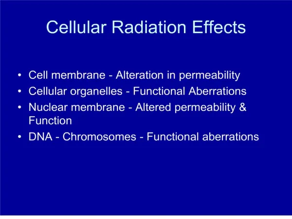
ASEN-5335 Aerospace Environments -- Radiation Effects on Space Systems UV photons interacting with complex organic polymers can cause material degradation and change the properties of materials. The absorption of UV radiation by organic molecules leads to highly reactive excited states that react on a molecular level and lead to macroscopic changes in the surface properties. Temperature of a spacecraft is proportional to the solar absorptance, and too great a temperature increase can lead to loss of the spacecraft. Silver Teflon Careful selection of radiation-resistant, external surface materials can be an important consideration in spacecraft design. Flight data from the SCATHA Satellite indicating that the solar absorptance of thermal control coatings increases under UV radiation.
ASEN-5335 Aerospace Environments -- Radiation Effects on Space Systems Charged-Particle Interactions Rutherford (Coulomb) Scattering Nuclear Interactions • Impacting particle actually interacts with the atomic nucleus • Can result in transmutation (conversion of on element or isotope to another) • Recoil atoms from displacement can cause significant damage • Long-term exposure can make spacecraft material radioactive • Usually dominates • Charged particle interacts with electric field of target atom • Results in both excitation and ionization of atomic electrons • For sufficiently energetic impacts, can displace atoms within the lattice structure
ASEN-5335 Aerospace Environments -- Radiation Effects on Space Systems UNITS The official SI unit of radiation is the Gray (Gy) 1 Gray = radiation which deposits 1 J/Kg of material You may be more familiar with the Rad (radiation absorbed dose) or Roentgen: 1 Rad = radiation which deposits .01 J/Kg of material 1 Roentgen = amount of gamma radiation or X-rays that will produce one electrostatic unit of charge of either sign (2.08 x 10⁹ ion pairs) in one cubic centimeter of air at standard temperature and pressure.
ASEN-5335 Aerospace Environments -- Radiation Effects on Space Systems X particles cm-2 s-1 = Rad s-1 Radiation dose is the amount of energy deposited in a material. Aluminum Two major factors in the determination of radiation damages: (1) total dose over the life of a material; and (2) dose rate, the rate at which energy is deposited.
ASEN-5335 Aerospace Environments -- Radiation Effects on Space Systems This is why metals are used to protect the other materials. Different materials have different susceptibilities to damage: Radiation dose is dependent on the type of radiation and its energy in addition to the material itself.
ASEN-5335 Aerospace Environments -- Radiation Effects on Space Systems Note: “stopping cross-section”, not in units of area. where n is the material density (cm-3). The range of the particle in the absorbing material can be calculated by integrating the above to give: STOPPING CHARGED PARTICLES By considering the electrostatic forces involved, one can calculate the KE lost by a charged particle traversing matter, leading to the definition of stopping power. Experimental data also exist. Stopping power is the amount of energy lost by a particle per unit length of path through the material. This is sometimes called linear energy transfer (LET):
ASEN-5335 Aerospace Environments -- Radiation Effects on Space Systems Note units Sample Stopping Power Curves for Ions and Electrons in Silicon
ASEN-5335 Aerospace Environments -- Radiation Effects on Space Systems Typical shielding thickness 40-80 mils (0.1-0.2 cm Sometimes Penetration Depth is used as a Measure Penetration Depth: maximum distance a particle of a given energy can penetrate Note that: A 1-MeV electron penetrates over 100 times more shielding (≈0.2 cm) than a 1-MeV proton (≈0.0015 cm) Penetration depth is a rough estimate of the minimum cutoff energy for a given thickness of spacecraft shielding, and hence the effectiveness of this shielding.
ASEN-5335 Aerospace Environments -- Radiation Effects on Space Systems i.e., 40 mils Al ineffective in stopping 5 MeV electron Sometimes Fraction of Fluence or Flux Transmitted as Function of Depth (of Shielding Material) is used as a Measure • Density of aluminum is used as standard reference • To first order the amount of shielding scales with the density of the material • Electrons above a few hundred keV can penetrate a significant amount of material 1 mil = .001 inches For very high-energy (relativistic) electrons, Brehmsstrahlung radiation produces additional damage in materials.
ASEN-5335 Aerospace Environments -- Radiation Effects on Space Systems Satellite Anomalies Most Satellite Anomalies are Unrelated to the Space Environment On-orbit anomaly records (guidance, navigation and control only) for satellites launched between 1990 and 2001 Information on satellite anomalies is not widely shared within the industry or with the public. From the July 11, 2002 Space Daily: “Satellite Anomalies Pushing Insurance Rates Up”
ASEN-5335 Aerospace Environments -- Radiation Effects on Space Systems Satellite Anomaly Example: TERRA – MISR Data Before Shutter Opening 3-16 Feb 2000 Besides light, energetic particles can generate a signal in a CCD. MISR - Multi-Angle Imaging Spectro-Radiometer
ASEN-5335 Aerospace Environments -- Radiation Effects on Space Systems Satellite Anomaly Examples: TOPEX – 1992-1998 and TERRA-MODIS 2001 Geomagnetic field contours near 1,300 Km altitude and superposed anomaly locations for TOPEX (red dots) and TERRA-MODIS temporary failure location (star) in June 2001.
ASEN-5335 Aerospace Environments -- Radiation Effects on Space Systems Satellite Anomaly Example: TDRS Tracking and Data Relay Satellite (TDRS) is one of a network of communications satellites of the Tracking and Data Relay Satellite System (TDRSS) used by NASA and agencies for communication to satellites or the International Space Station. The system was designed to replace an existing network of ground stations that had supported all of NASA's manned flight missions. The prime design goal was to increase the time spacecraft were in communication with the ground and improve the amount of data that could be transferred. In the mid-1980s, NASA’s TDRS-1 satellite was launched into GEO to begin replacing the global tracking antenna network with an array of satellites to relay commands to LEO satellites and Shuttles. Eventually there were to be 4 such satellites operating in a constellation to provide uninterrupted communications. However, experiences with the first satellite of this series (see next two slides) were not good. Eventually convincing evidence was produced that the many anomalous events on TDRS-1 were a product of susceptibility to galactic cosmic rays and to solar energetic protons and heavier ions. One of the engineers involved in Albuquerque with operating TDRS-1 characterized the 93L422 RAM chip as “a flying solid state cosmic ray detector”. At some expense the chips were replaced in TDRSS-2 to –4 and greatly reduced the number of anomaly events (but did not eliminate all of them). NASA continued using the RAM chip at least through the construction and launch of the Hubble Space Telescope (HST) which has problems similar to those of TDRS-1 when HST passes through the SAA. Slide Credit: Joe Allen, NOAA/NGDC -- http://www.scostep.ucar.edu/archives/gomac_2002/GOMACTalk.html
ASEN-5335 Aerospace Environments -- Radiation Effects on Space Systems TDRS-1 anomalies during one of several hard-spectrum proton flare/CME events in October 1989. Slide Credit: Dan Wilkinson and Joe Allen, NOAA/NGDC -- http://www.scostep.ucar.edu/archives/gomac_2002/GOMACTalk.html
ASEN-5335 Aerospace Environments -- Radiation Effects on Space Systems TDRS-1 was an unintended probe of the energetic particle environment at GEO altitude The 5-year time-series of TDRS-1 SEU events shows both a susceptibility to galactic cosmic rays (upper panel - long period variation out of phase with the sunspot cycle) and to solar energetic particle events (many spikes in 1989). Slide Credit: Joe Allen, NOAA/NGDC -- http://www.scostep.ucar.edu/archives/gomac_2002/GOMACTalk.html
ASEN-5335 Aerospace Environments -- Radiation Effects on Space Systems Computer codes exist that will convert incident energetic particle fluxes into radiation dose behind a specified shield thickness, i.e., SHIELDOSE http://www.spenvis.oma.be/spenvis/help/background/shieldose/shieldose.html SHIELDOSE Calculates, for arbitrary proton and electron incident spectra, the dose absorbed in small volumes of different detector materials for the following aluminium shield geometries: 1. in a semi-infinite plane medium, as a function of depth; irradiation is from one side only (the assumed infinite backing effectively insures this). 2. at the transmission surface of a plane slab, as a function of slab thickness; irradiation is from one side only. 3. at the center of a solid sphere, as a function of sphere radius; irradiation is from all directions. CALCULATING RADIATION DOSE A crude measure of damage by penetrating energetic particles is the radiation dosage measured in rads.
ASEN-5335 Aerospace Environments -- Radiation Effects on Space Systems In many cases a tradeoff exists between orbit choice and system lifetime. Effects of atmospheric shielding “hard” Range of total dose variability for various microelectronic devices “soft” Accumulated dose over 5-yr mission due to radiation belt particles .1 inch = 100 mils
ASEN-5335 Aerospace Environments -- Radiation Effects on Space Systems Total accumulated dose depends on orbit altitude, orientation and time. Total ionizing dose (TID) for satellites typically ranges between 10 and 100 krad (Si). *total 4mm Al shielding
ASEN-5335 Aerospace Environments -- Radiation Effects on Space Systems Optimal Design Point Radiation Dose For Different Al Shield Thicknesses, LEO Note: Protons dominate in general
ASEN-5335 Aerospace Environments -- Radiation Effects on Space Systems Optimal Design Point Geosynchronous Orbit Dose for Different Al Shield Thicknesses (8-Year Mission) Note: electrons dominate for thinnest shields; also, higher doses than LEO Rads/year
ASEN-5335 Aerospace Environments -- Radiation Effects on Space Systems The CRRESRAD Model Based on the CRRES (Combined Release and Radiation Effects Satellite) Mission. -- complete complement of radiation environment sensors (dosimeter, e- and H+ monitors, etc.) -- July 25, 1990 - 12 October 1991; 18.1°, 350 km x 33,000 km orbit PC-based software program that provides estimates of the dose behind 4 shielding thicknesses of hemispherical aluminum shielding (0.57, 1.59, 3.14, and 6.08 gm/cm2) --- corresponding to electron energies > 1, 2.5, 5, and 10 MeV and proton energies > 20, 35, 52, and 75 MeV. Different levels of magnetic activity are included. Differences between CRRESRAD and equivalent results for AP8 and AE8 can sometimes be substantial. See http://www.kirtland.af.mil/library/factsheets/factsheet.asp?id=7899 for a complete list of available “AF-GEOSPACE” user-friendly, graphics-intensive software program bringing together many of the space environment models, applications, and data visualization products developed by the Air Force Research Laboratory
ASEN-5335 Aerospace Environments -- Radiation Effects on Space Systems Some Additional Slides for Reference
ASEN-5335 Aerospace Environments -- Radiation Effects on Space Systems flux to dose conversion factor (see homework) f(E) shielding- attenuated flux particles cm-2MeV-1 energy deposited in target for particle of initial energy E Total dose at energy E (rads MeV-1) Jparticle-1MeV-1 Total dose over all energies Radiation-Dose Environment Within a Spacecraft: Basic Mathematical Steps fo(E) ambient flux One then needs to repeat the above process over different parts of the spacecraft, and integrate over the expected radiation conditions for the expected spacecraft orbit during the period of the desired orbital operations (mission lifetime). shielding unit area dA target
ASEN-5335 Aerospace Environments -- Radiation Effects on Space Systems Case Study: The Clementine Spacecraft Lunar Transfer Orbit • Clementine was a DoD/NASA mission designed to map the moon and an Earth orbit-crossing asteroid. • Also tested the effects of the radiation environment on a number of microelectronic systems. • Clementine left behind its lunar transfer stage in a unique, highly elliptical orbit that passed repeatedly through the trapped radiation belts. • This interstageand Clementine were both instrumented with radiation dosage and SEU detectors. They carried boxes of microelectronics components for direct exposure to the radiation environment. • A detailed radiation environment prediction was required to allow identification of radiation sensitive parts and to determine appropriate replacement parts or provide enhanced protective measures. • It was also desired to predict the performance of the systems and test components in the radiation environment. • These are all typical requirements for a space mission and illustrate the wide range of potential requirements that a trapped radiation model might be expected to address.
ASEN-5335 Aerospace Environments -- Radiation Effects on Space Systems Five geometries were considered: Usually most appropriate Steps for Obtaining Clementine Dose Estimates • B and L coordinates were calculated for the orbit. • Particle integral flux as a function of energy was computed from the AE8/AP8 models, and summed over mission lifetime to give the total integral fluence spectrum in terms of energy and particle species. • These spectra were inserted into the commercially-available NOVICE code to compute total energy deposited at a point as a function of shield thickness, composition (Aluminum for shield and Si for dose site) and geometry.
ASEN-5335 Aerospace Environments -- Radiation Effects on Space Systems • A set of orbital data for the portions of the Clementine orbit • within 11 RE was assembled. (AE8 models are only useful • inside ~11 RE ; ~6 RE for AP8): • 1) 1994/01/24 (01:48)—1994/01/26 (01:00) (initial parking orbit). • 2) 1994/01/26 (01:00)—1994/01/30 (06:44) (Earth–moon transfer injection). • 3) 1994/01/30 (07:00)—1994/02/09 (12:00) (Earth–moon transfer orbit). • 4) 1994/02/09 (12:00)—1994/02/21 (01:09) (Earth–moon transfer orbit). • 5) 1994/05/03 (13:17)—1994/05/15 (12:00) (Earth gravity-assist flyby). • 6) 1994/05/15 (12:00)—1994/05/27 (18:08) (Earth gravity-assist flyby). • A range of doses was calculated for the different geometrical considerations, SSMIN & SSMAX, shielding thickness and particle type. • Radiation design for Clementine used a radiation design margin (RDM) = 4 (i.e., estimated dose values were multiplied by 4 to provide a worst case design requirement for parts). Examples follow
ASEN-5335 Aerospace Environments -- Radiation Effects on Space Systems nominal Radiation dosage from the trapped proton environment (AP8) for solar quiet conditions (worst-case condition for protons) and for the first Earth-moon transfer orbit.
ASEN-5335 Aerospace Environments -- Radiation Effects on Space Systems Note wider variation in results for electrons. nominal Radiation dosage from the trapped electron environment (AP8) for solar active conditions (worst-case condition for electrons) and for the first Earth-moon transfer orbit.
ASEN-5335 Aerospace Environments -- Radiation Effects on Space Systems Mission summary plot for the total radiation dose for the Clementine interstage. This assumes a 450-day mission and 95% confidence flare environment.