Download
1 / 48
480 likes | 581 Views
ILC Accelerator. Kaoru Yokoya (KEK) 2013.12.13 KIAS. TDR. Global TDR Event on Jun.12.2013 Tokyo CERNFNAL TDR handed to LCC Director Lyn Evans. Site Down-selection. Down selection to Kitakami site announded in August end. ILC Layout. Electron source Positron source Damping Rings.

E N D
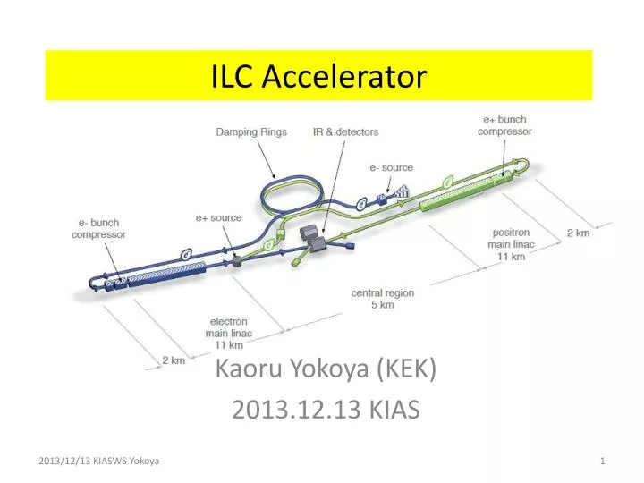
ILC Accelerator Kaoru Yokoya (KEK) 2013.12.13 KIAS
TDR • Global TDR Event on Jun.12.2013 • TokyoCERNFNAL • TDR handed to LCC Director Lyn Evans
Site Down-selection • Down selection to Kitakami site announded in August end
ILC Layout • Electron source • Positron source • Damping Rings • RTML • Main linacs • BDS
Main Linac • Key area of ILC • ~2/3 of the total cost • TDR specification • Gradient at vertical test • Average 35MV/m • Accept cavities > 35 -20% = 28MV/m • Q0 > 0.8x10¹⁰ at 35MV/m • yield > 90% (Up to 2 surface treatment passes) • Average operating gradient 31.5MV/m • Accept the range +/- 20% • Q0 > 1xx1010 at 31.5MV/m
Progress in 1.3 GHz ILC Cavity Production A. Yamamoto, May2013, ECFA13 • Progress in EXFEL (800 cavity construction as of 2012/10): (courtesy by D. Reschke: the 2nd EP at DESY) • RI: 4 reference cavities with Eacc > 28 MV/m, (~ 39 MV/m max.) • Zanon: 3 reference cavities with Eacc > 30 MV/m ( ~ 35 MV/m max.)
Global Cavity Gradient Results - EU 3 slides from R.Geng, LCWS12 DESY data, D. Reschke et al., SRF2009, TUPPO051.
Global Cavity Gradient Results - Americas JLAB data, R.L. Geng et al., IPAC2011, MOPC111.
Global Cavity Gradient Results - Asia KEK data, Y. Yamamoto et al., IPAC2012, WEPPC013.
High Gradient Accelerating Cavity > 16000 cavities needed for 500GeV Production yield: 94 % at > 28 MV/m, Achieved Average gradient: 37.1 MV/m
System Viability Proof ILC Spec: 5.8mA, 1ms DESY: FLASH • SRF-CM string + Beam, • ACC7/PXFEL1 < 32 MV/m > • 9 mA beam, 2009 • 800ms, 4.5mA beam, 2012 KEK: STF • S1-Global: complete, 2010 • Cavity string : < 26 MV/m> • Quantum Beam : 6.7 mA, 1 ms, • CM1 & beam, 2014 ~2015 FNAL: NML/ASTA • CM1 test complete • CM2 operation, in 2013 • CM2 + Beam, 2013 ~ 2014 A. Yamamoto, JPS meeting, Mar.2013
Euro-XFEL Status E.Kako, 2013/12/05, KEK
Europe - XFEL cavity production As of 11.09.2013 Num. of cavities: vendor 1 23 vendor 2 56 2nd pass: additional high-pressure rinse usable gradient: X-ray limited (dark current) Maximum gradient D. Reschke, LCWS13
US – Fermilab CM-2 CM-2 features all high gradient cavities (> 35 MV/m) Cryomodule is installed and cold. Commissioning has started – no results yet New 500 W 2K refrigerator operational M.Harrison, LCWS13
Cryomodule Production– Fermilab & JLAB High Q_0 cryomodule with reduced cryogenics operating costs: Improved cooling capability New cavity surface processing recipe Improved magnetic shielding Adiabatic cool-down process M.Harrison, LCWS13
US – LCLS II • 4 GeV CW SRF Linac based FEL based on ILC cavities at SLAC • 35 cryomodules – 280 cavities • Gradient 16 MV/m; Q0 2e10 at 1.8K • Beam power 1.2 MW max • Cryogenic power 5.5 MW • Located in the upstream end of the • existing 3km tunnel 550 m ~ LCLS-II Length L2 j = -21° V0=1447 MV Ipk = 50 A Lb = 0.56 mm L3 j = 0 V0=2409 MV Ipk = 1.0 kA Lb = 0.024 mm L0 j= * V0=97 MV Ipk = 12 A Lb = 2.0 mm L1 j =-22° V0=220 MV Ipk = 12 A Lb =2.0 mm HL j =-165° V0 =55 MV CM01 CM2,3 CM15 CM35 CM04 CM16 3.9GHz LTU E = 4.0 GeV R56 = 0 sd 0.016% 2-km LH E = 98 MeV R56 = -5 mm sd = 0.05 % BC1 E = 250 MeV R56 = -55 mm sd = 1.4 % BC2 E = 1600 MeV R56 = -60 mm sd = 0.46 % GUN 0.75 MeV 100-pC machine layout: Oct. 8, 2013; v21 ASTRA run; Bunch length Lb is FWHM Linac and compressor layout M.Harrison, LCWS13
10 year Evolution of STF at KEK up to ~ 420MeV E.Kako, 2013/12/05, KEK
Remaining Technical Issues for Main Linac • Cavity production yield as high as possible • Improvement of cavity performance in cryomodule • Finalize the coupler design (TTF3/XFEL or STF2 type) • Confirmation of the reliability in long term operation (coupler, tuner) • Further cost reduction in mass production • Higher cavity gradient for Ecm>500GeV
Positron Source 3 possible shemes of positron beam generation • Undulatormethod(adopted in ILCbaseline) • Conventional Method • Hit a few GeV electrons on a target, and collect the generated positrons • adopted in many accelerators, well established • Issues in the application to ILC • Survivability of the target OK • Emittance of the generated positron OK (improved DR optics) • Transport to DR entranceunder study • No polarized positron • Laser-Comptonmethod(far future)
ILCDesign(undulator method) • Electron energy>150GeV • Undulator • At the end of the electron linac • Helical, superconducting • Length ~150m (~230m when highly poloarized positron is needed) • K=0.92, l=1.15cm, (B=0.86T on the axis) • beam aperture 5.85mm (直径) • Target: rotating titanium alloy • Flux Concentratorfor positron capture • Normal-conducting accelkeration up to 400MeV • Polarization~30%(~60% with photon collimatorand longer undulator)
Positron Yield • UndulatoraT the end of electron l;inac • positron yield depends on the electron energy (=center-of-mass energy / 2) • Positron insufficient for Ee < 150GeV • To restore the luminosity, the electron linac is operated at 10Hz: • 5Hz for positron production • 5Hz for collision
Target • Wheel of Titanium alloy, diameter 1m • Must rotate at 100m/s (2000 rpm) in vacuum • Under test at LLNL using Ferromagnet seal • Still unsatisfactory • Outgassing spikes still being observed • More works needed • market products don’t work
Positron Capture • Baseline : Captureby flux concentrator • No change since RDR • But lower the max field5T3.5T(simulation showed sufficient) • Problem: pulse duration 1ms • Also being tested at LLNL • Can be replaced with QWT (Quarter Wave Transformer) • But requires longer undulaort (x1.6倍) • Heavier load on the target
Conventional e+ Source for ILC Normal Conducting Drive and Booster Linacs in 300 Hz operation e+ creation go to main linac 20 triplets, rep. = 300 Hz • triplet = 3 mini-trains with gaps • 44 bunches/mini-train, Tb_to_b = 6.15 n sec 2640 bunches/train, rep. = 5 Hz • Tb_to_b = 369 n sec Drive Linac Several GeV NC 300 Hz Booster Linac 5 GeV NC 300 Hz DR Tb_to_b = 6.15 n sec Target Amorphous Tungsten Pendulum or Slow Rotation 2640 bunches 60 mini-trains Time remaining for damping = 137 m sec T.Omori
Bunch Pattern Moving target still needed but much slower =132 bunches <-- the 100 ns gap is required to cure an e- cloud problem in e+ DR. T.Omori
Issues of the Positron System • Undulator Scheme • Rotating target and flux concentrator development at LLNL • Photon collimator for higher polarization • Conventional Source • “conventional” but still needs some more R&D • High current, high rep rate driver linac • Moving target (<~ 5m/s) • Flux concentrator • Overall simulation • Confirm the positron yield • Including capture, bunch compression, beamloading & energy compression • Choice of undulator/conventional will not affect the tunnel shape • The driver electron linac for Conventional Source can be installed in the space for undulator+photon drift in the ubdulator scheme • Therefore, we have some couple of years to the deadline of the choice
Moving Target • <~5m/sec required (1/20 of undulator scheme) • 2 possible schemes being developed at KEK 5Hz pendulum with bellows seal rotating target with ferromagnetic seal bellows seal air ferromagnetic fluid seal vacuum air vacuum main issue: vacuum main issue: life of bellows First step prototype being tested
Damping Rings • Requirements • gex = 5.5 mm, gey = 20nm • Time for damping 100ms • First step 1312 bunches, maximum 2625 bunches • bunch-by-bunch injection/extraction • Circumference ~3km • 1 ring for each of electron and positron in the first step • bunch interval ~6ns • (if necessary) add one more positron ring when going to 2625 bunches • depends on electron cloud • 1 electron ring in any case (bunch interval 3ns) quadrupole section dipole section
Electron Cloud Instability • Has been studied at CESR-TA by international team • Gave recommendation for the mitigation method (table below) • Arc and wiggler sections requires antichamber • Full power in 3.2km ring needs aggressive mitigation plan • No significant difference between 6.4km with 2600 bunches and 3.2km with 1300 bunches ECLOUD`10 (October 13, 2010, Cornell University)
Damping Ring Vacuum Chamber • Following the recommendation by CESR-TA team, ILC adopts the following chambers • Other instabilities are less serious in positron damping ring • FII (Fast Ion Instability) is the most important in the electron ring
BDS(Beam Delivery System) • Ultimate role of BDS is to focus the beam at the IP, but there lots of devices to do this • Machine Protection System • Tune-up/emergency dump • Collimator • Beam diagnostics section (beam energy, emittance, polarization) • Muon absorber • Crab cavity • Feedback system • Beam diagnostics after IP (beam energy, polarization) • Main beam dump
ATF2: Beam Focusing Test Facility at KEK The ATF2 has been designed, constructed and operated under the international collaboration. ATF2 DR LINAC 50 m 120 m
ATF2 Goals • Beam size at 1.3GeV • Goal 37nm • ~65nm achieved • Beam positron stabilization to a few nm by feedback
IP Feedback • Bunch interval is long enough for intra-train digital feedback • Advantage of SC collider • Large disruption parameter • Dy = 25
Issues on BDS • ATF2 • Beam focus by another factor 2 • Stabilization to ~2nm • Design check • beam dumpline • impedances • Commissioning strategy • Is the IP beam size monitor needed? • Access to IR hall • Access slope in TDR (mountain region) but, is vertical shaft possible?
Site Specific Design Kitakami-site cross section Damping Ring Detector Hall Ring To Main Linac (RTML) PM+13 PM+12 PM+10 PM-ab PM+8 e+ ML Surface Structures e- Source PM-8 Existing surface road PM-10 PM-12 (Slope <7%) PM-13 e+ Source Access Hall PX Access Tunnel (Center Campus) (Slope <10%) e- Main Linac (ML) Existing road (The background photo shows a similar site image, but not the real site.) RTML turn-around
CFS Plan Towards the Construction Start 2013 2014 2015 2016 2017 2018 2019 A.Enomoto, LCWS13
From the LCWS Conclusion on CFS • The selected site satisfies the TDR conventional designs without any fundamental issues • The remaining issues yet to be worked out (such as the path length and positron scheme) will not affect the underground construction and surface facility layout • Intensive geotechnical study of the detector hall by a Japanese company. This will be checked with the previous European IR hall analysis
LCC Pre-IL Accelerator Organization Project Management LC Project Office (KEK) Technical Board Baseline, Schedule Cost, EDMS SRF ww Accelerator Design & Integration ww Conventional Facilities ww Main Linac ww Electron Source ww Cryogenic Support Japan Beam Delivery ww Positron Source ww Safety Japan Machine-Detector Interface ww Damping Rings ww Electrical Support Japan RTML & bunch compressor ww Mechanical Support Japan Domestic Programs & System Tests Controls & Computing Japan
Summary • Site down-selected to Kitakami, Japan • Site-specific design going to start • There are some remaining issues • positron • Final focus (ATF2) • New organization under LCC-ILC box (chaired by Mike Harrison) is being formed