Distributed Network Protection (DNP) Architecture Study
This study explores the distributed network protection architecture, including high-level models, basic nodes, and protection mechanisms. It covers PBB and PBB-TE networks, MAC address analysis, and DRNI connectivity.

Distributed Network Protection (DNP) Architecture Study
E N D
Presentation Transcript
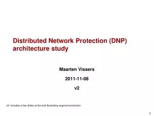
Distributed Network Protection (DNP) architecture study Maarten Vissers 2011-11-08 v2 v2: includes a few slides at the end illustrating segment protection
Contents • Introduction 3 • Legend 4 • High level models of PIP+CBP, PNP, PEP+CNP, CNP, CEP 5 • High level & basic models of IBBEB nodes 8 • High level & basic models of PEB/PB nodes 10 • PBB/PBB-TE network with IBBEB nodes 12 • PBB Domain with restorable BVLAN Ethernet Connections (EC) 13 • BVLAN U for unprotected SVLAN ECs • BVLAN A & B for protected SVLAN ECs • Load sharing between portal nodes, BVLAN end point blocking • Distributed Restorable BVLAN connected to DRNI • PBB-TE Domain with protected TESI connections 17 • TESI U1,U2 for unprotected SVLAN ECs • TESI A1,A2,A3 & B1,B2,B3 for protected SVLAN ECs • Load sharing between portal nodes, TESI end point blocking • Distributed TESI Protection connected to DRNI • Port filtering entities location in CBP 22 • PBB Domain with G.8031 SNC protected SVLAN EC 24 • Compound view – BVLAN, TESI, SVLAN restoration/protection connected to DRNI 26 • Impact of single switch fabric? 31
Introduction • The following slides focus on the distributed network protection (DNP) functionality and associated MAC addresses in the portal nodes of a DRNI protected Ethernet ENNI. These slides complement the “DRNI Data Plane Model I/II Comparison & MAC Address Values in DRNI” slides (axbq-vissers-drni-data-plane-model-I-and-II-comparison-1011-v00.pptx) . • The simplest DRNI configuration is assumed, including two nodes in a portal • A portal supports DRNI protected SVLAN ECs and unprotected SVLAN ECs (as per MEF requirement); unprotected SVLAN ECs are considered to be outside DNRI control • Network domain is assumed to be PBB/PBB-TE and portal nodes are IBBEB nodes, supporting restorable MP2MP BVLAN ECs and protected P2P TESIs • Deployment of alternative network domain technologies (MPLS(TP), SDH, OTN) and portal nodes (TB) is addressed in a next version. In such TB nodes the B-Component and PIPs are replaced by MPLS(TP), SDH or OTN Network Ports connected to ‘MPLS LSP Relay’, ‘SDH VC-n Relay’ or ‘OTN ODUk Relay’ functions and MPLS(TP), SDH or OTN specific ‘provider network ports’. • MAC address requirement is investigated (to some extend) to understand which functions must use the PIP/CBP port’s EUI48 values, which functions may use these values and which functions must not use these values; further analysis is to be added in a next version
Legend • The configurations in this presentation require the use of a more compact modelling method than provided by the 802.1Q models • For this reason the next slides present alternative presentations for the various XXP ports specified in 802.1Q • Those alternative presentations focus on the MEP, MIP and multiplexing/demultiplexing (MUX) functionality within those XXP ports and port pairs • The alternative presentation of the PIP-CBP port pair assumes the support of the basic functionality specified in clause 5.7/802.1Q, supporting single domain PBB networks with IB BEB and BCB nodes
Legend 19.2/3/5 19.2/3/5 SVLAN MEP & MIP PIP 6.9 6.9 6.9 6.9 6.9 6.9 6.9 6.9 6.9 6.9 6.9 6.9 SVLAN MEP/MIP 8.5 8.5 8.5 8.5 8.5 8.5 8.5 8.5 8.5 8.5 8.5 8.5 SVLAN mux 6.10 6.10 SVLAN to BVLAN/TESI muxes BVLAN/TESI MEP 6.14 6.14 6.14 6.14 6.11, 9.5c 6.11, 9.5c CBP SVLAN MEP/MIP BVLAN/TESI MEP 19.2/5 19.2/5 SVLAN mux & TESI protection switch MUX MUX MUX W & P TESI MEPs MUX 19.2/3/5 19.2/3/5 BVLAN /TESI MEP & MIP BVLAN/TESI MEP/MIP 6.9, 9.5b 6.9, 9.5b BVLAN mux BVLAN/TESI to Link mux PNP 8.5 8.5 Link MEP 19.2 Link MEP 19.2 6.7 6.7 PHY MEP 802.3 802.3
Legend 19.2/3/5 19.2/3/5 SVLAN MEP & MIP SVLAN MEP/MIP 6.9, 9.5b 6.9, 9.5b PNP SVLAN mux SVLAN to Link mux 8.5 8.5 Link MEP 19.2 Link MEP 19.2 6.7 6.7 PHY MEP 802.3 802.3 MUX MUX 19.2/3/5 19.2/3/5 CVLAN MEP & MIP PEP 6.9, 9.5a 6.9, 9.5a CVLAN MEP/MIP 8.5 8.5 CVLAN to SVLAN mux CVLAN mux 6.14 6.14 SVLAN MEP 6.14 6.14 6.9, 9.5b 6.9, 9.5b CNP 19.2/5 SVLAN MEP 19.2/5
Legend 6.9, 9.5a 6.9, 9.5a CVLAN to Link mux CVLAN mux 8.5 8.5 Link MEP 19.2 Link MEP 19.2 CEP 6.7 6.7 PHY MEP 802.3 802.3 MUX MUX 19.2/3/5 19.2/3/5 SVLAN MEP & MIP SVLAN MEP/MIP 6.9, 9.5b 6.9, 9.5b CNP SVLAN mux SVLAN to Link mux 8.5 8.5 Link MEP 19.2 Link MEP 19.2 6.7 6.7 PHY MEP 802.3 802.3
High level model of IBBEB nodes ENNI Intra-DAS BVLAN/TESI MEP Link MEP SVLAN mux SVLAN MEP/MIP SVLAN EC Relay Intra-DAS SVLAN MEP/MIP SVLAN mux BVLAN/TESI MEP BVLAN EC/TESI Relay BVLAN/TESI MEP/MIP BVLAN/TESI mux Link MEP INNI
Basic model of IBBEB nodeswithout illustrating intermediate MEP/MIP functions ENNI Intra-DAS SVLAN EC Relay Intra-DAS BVLAN EC/TESI Relay INNI
High level model of PEB/PB nodes PEB functionality UNI Link MEP CVLAN mux Intra-DAS ENNI UNI CVLAN EC Relay Link MEP SVLAN mux Link MEP SVLAN mux CVLAN MEP/MIP CVLAN mux SVLAN MEP SVLAN MEP/MIP SVLAN MEP/MIP SVLAN EC Relay SVLAN MEP/MIP SVLAN mux Link MEP INNI
Basic model of PEB/PB nodeswithout illustrating intermediate MEP/MIP functions PEB functionality UNI UNI ENNI Intra-DAS CVLAN EC Relay SVLAN EC Relay INNI
PBB/PBB-TE Network with IBBEB nodes INNI Link end points SVLAN EC Relay BVLAN/TESI end points BVLAN EC/TESIRelay Link end points PBB, PBB-TE domain (note) Link end points Link end points BVLAN EC/TESIRelay BVLAN EC/TESI Relay BVLAN/TESI end points BVLAN/TESI end points SVLAN EC Relay SVLAN EC Relay ENNI ENNI
animated PBB Domain with BVLAN ECs BVLAN A for protected SVLAN ECs has active endpoint at either the right, or the left portal node. The other BVLAN endpoint is blocked. The two BVLAN endpoints form one virtual endpoint. BVLAN U for unprotected SVLAN ECs has active endpoints at left and right portal nodes. INNI SVLAN EC Relay BVLAN B for protected SVLAN ECs has active endpoint at either the left, or the right portal node. The other BVLAN endpoint is blocked. The two BVLAN endpoints form one virtual endpoint. BVLAN ECRelay BVLAN U BVLAN A BVLAN B Intra-Network BVLAN Intra-DAS BVLAN BVLAN ECRelay BVLAN ECRelay Blocked BVLAN A endpoint Blocked BVLAN B endpoint B-MAC addresses of left & right BVLAN U endpoints is different SVLAN EC Relay SVLAN EC Relay B-MAC addresses of left & right BVLAN A endpoints is the same B-MAC addresses of left & right BVLAN B endpoints is the same Intra-DAS Link
Load sharing at portal nodes • BVLAN AandB are used to support load sharing of protected SVLAN ECs by the two portal nodes • Under fault free conditions, 50% of the SVLAN EC traffic will pass through the left portal node to the ENNI and the other 50% will pass through the right portal node • The figure in the previous slide illustrates that BVLAN A and B are both having an end point on the domain top edge node to illustrate load sharing. To support multipoint SVLAN ECs between any sub set of edge nodes it is typically necessary that a BVLAN is connected to all IB BEB nodes in a domain. BVLAN A and B most likely will have end points on each edge node as such.Note: For load balancing at the portal nodes, it is not necessary to distribute the SVLAN ECs in each edge node over both BVLAN A and B. • Unprotected SVLAN ECs can not be supported by BVLAN Aor B due to blocking of BVLAN end point at one of the two portal nodes • QUESTION: How to block a BVLAN end point; i.e. prevent that BVLAN OAM generated on the CBP will enter the BVLAN Relay function? • BVLAN ECs are set up under MSTP/MVRP control. A/B are dynamic connections. MSTP/MVRP will restore BVLAN A/B ECs if it receives a trigger condition. Triggers are e.g. ‘active gateway failed’ and request from DRNI.
Distributed Restorable BVLAN connected to DRNI B A U B A U X W P W P W P W P SVLAN EC Relay SVLAN EC Relay SVLAN EC Relay SVLAN EC Relay Half-DAS Half-DAS Half-DAS Half-DAS X Intra-DAS BVLAN Intra-DAS BVLAN X ENNI ENNI ENNI ENNI Active Gateway Standby Gateway Active Gateway Standby Gateway Standby Gateway Active Gateway Active Gateway Standby Gateway Right portal node failure or ENNI + Intra-DAS BVLAN failure Normal state, no failures
Distributed Restorable BVLAN connected to DRNI B A U B A U W P W P W P W P SVLAN EC Relay SVLAN EC Relay SVLAN EC Relay SVLAN EC Relay Half-DAS Half-DAS Half-DAS Half-DAS Intra-DAS BVLAN Intra-DAS BVLAN X X ENNI ENNI ENNI ENNI Active Gateway Standby Gateway Standby Gateway Active Gateway Active Gateway Standby Gateway Standby Gateway Active Gateway Right ENNI failure Left ENNI failure
animated PBB-TE Domain with TESI connections TESI A1,A2,A3 for protected SVLAN ECs has active protected endpoint at either the right, or the left portal node. The other protected TESI endpoint is blocked. The two protected TESI endpoints form one virtual protected endpoint. TESI U1,U2 for unprotected SVLAN ECs has active endpoints at left and right portal nodes. INNI SVLAN EC Relay TESI B1,B2,B3 for protected SVLAN ECs has active protected endpoint at either the left, or the right portal node. The other protected TESI endpoint is blocked. The two protected TESI endpoints form one virtual protected endpoint. W P P W TESIRelay U1 B1 U2 B2 TESI U1,U2 A2 A1 TESI A1,A2,A3 B3 TESI B1,B2,B3 A3 TESI A relay TESI B relay Intra-Network TESI TESIRelay TESIRelay Blocked TESI B protected endpoints Intra-DAS TESI Blocked TESI A protected endpoints W* P P* W W P* P W* ESP-MAC address of left & right TESI U endpoints is different SVLAN EC Relay SVLAN EC Relay ESP-MAC address of left & right TESI A endpoints is the same ESP-MAC address of left & right TESI B endpoints is the same Intra-DAS Link
TESI W & P connection configurations P W Working TESI = A1 Protection TESI = A2+A3 TESIRelay P* W P W* ESP-DA = @A, ESP-VID = a2 ESP-DA = @A, ESP-VID = a1 A2 A1 A3 ESP-DA = @A, ESP-VID = a3 ESP-VID = a4 TESI A drop TESI A relay ESP-VID Translation? TESIRelay DNP Control Protocol TESIRelay P* W P W* @A @A P W TESIRelay Working TESI = A1+A3 Protection TESI = A2 P* W P W* ESP-DA = @A, ESP-VID = a2 ESP-DA = @A, ESP-VID = a1 A2 A1 A3 ESP-DA = @A, ESP-VID = a3 ESP-VID = a4 TESI A relayESP-VID Translation? TESI A drop TESIRelay TESIRelay DNP Control Protocol P* W P W* @A @A
Load sharing at portal nodes • TESI AandB are used to support load sharing of protected SVLAN ECs by the two portal nodes • Under fault free conditions, 50% of the SVLAN EC traffic will pass through the left portal node to the ENNI and the other 50% will pass through the right portal node • The figure in slide 17 illustrates that TESI A and B are both having an end point on the domain top edge node to illustrate load sharing.Note: For load balancing at the portal nodes, it is not necessary to that each edge node has a TESI A and B. For load balancing at portal nodes, some edge nodes may only have a TESI A and other edge nodes may only have a TESI B. • Unprotected SVLAN ECs can not be supported by TESI Aor B due to blocking of TESI end point at one of the two portal nodes • QUESTION: How to block a TESI end point; i.e. prevent that TESI OAM generated on the CBP will enter the TESI Relay function? • TESI connections are set up under network management control. A1/B1 and A2/B2 are static connections. Adding A3/B3 allows portal nodes to control relay or drop of incoming TESI frames. A3/B3 should have third/forth ESP-VID value.
Distributed TESI Protection connected to DRNI U1 B1 A2 A1 B2 U2 U1 B1 A2 A1 B2 U2 X B3 B3 A3 A3 P* W W* P W P* P* W W P* P W* P W* W* P SVLAN EC Relay SVLAN EC Relay SVLAN EC Relay SVLAN EC Relay Half-DAS Half-DAS Half-DAS Half-DAS X Intra-DAS TESI Intra-DAS TESI X ENNI ENNI ENNI ENNI Active Gateway Standby Gateway Active Gateway Standby Gateway Standby Gateway Active Gateway Active Gateway Standby Gateway Right portal node failure or ENNI + Intra-DAS TESI failure Normal state, no failures
Distributed TESI Protection connected to DRNI U1 B1 A2 A1 B2 U2 U1 B1 A2 A1 B2 U2 B3 B3 A3 A3 P* W W* P W P* P W* P* W `W* P W P* P W* SVLAN EC Relay SVLAN EC Relay SVLAN EC Relay SVLAN EC Relay Half-DAS Half-DAS Half-DAS Half-DAS Intra-DAS TESI Intra-DAS TESI X X ENNI ENNI ENNI ENNI Active Gateway Standby Gateway Standby Gateway Active Gateway Active Gateway Standby Gateway Standby Gateway Active Gateway Right ENNI failure Left ENNI failure
Port filtering entities Figures 22-2 and 22-4 in 802.1Q illustrate the location of the port filtering entities in a bridge port. How to apply these specifications in the case of a CBP?
Port filtering entities location in CBP? SVLAN EC Relay 19.2/3/5 19.2/3/5 19.2/3/5 19.2/3/5 SVLAN MEP & MIP Port filtering entities 8.6.1/2/4 Port filtering entities 8.6.1/2/4 Port filtering entities 8.6.1/2/4 Port filtering entities 8.6.1/2/4 19.2/3/5 19.2/3/5 19.2/3/5 19.2/3/5 SVLAN MEP & MIP PIP 6.9 6.9 6.9 6.9 6.9 6.9 6.9 6.9 6.9 6.9 6.9 6.9 6.9 6.9 6.9 6.9 6.9 6.9 6.9 6.9 6.9 6.9 6.9 6.9 8.5 8.5 8.5 8.5 8.5 8.5 8.5 8.5 8.5 8.5 8.5 8.5 8.5 8.5 8.5 8.5 8.5 8.5 8.5 8.5 8.5 8.5 8.5 8.5 6.10 6.10 6.10 6.10 6.14 6.14 6.14 6.14 SVLAN to BVLAN/TESI muxes D 6.14 6.14 6.14 6.14 6.11, 9.5c ISID 6.11, 9.5c ISID 6.11, 9.5c ISID Port filtering entitIes 8.6.1/2/4 C ISID BSI Relay BSI Relay BSI Relay 6.11, 9.5c B BSI Relay CBP ISID ISID ISID ISID ISID ISID Port filtering entities 8.6.1/2/4 ISID ISID ISID 19.2/5 Port filtering entities 8.6.1/2/4 ISID ISID ISID A BVLAN/TESI MEP 19.2/5 19.2/5 19.2/5 Port filtering entities 8.6.1/2/4 BVLAN EC/TESIRelay Under normal circumstances, the CBPs are Edge Ports for the BVLAN Ethernet connections and TESI connections and port filtering should not be performed; i.e. fixed forwarding (correct?). In a DRNI Portal with two nodes, BVLAN and TESI endpoints are duplicated (one in each portal node). Should port filtering be used to control which of the two endpoints is connected to a BVLAN/TESI? Or should we instead control the Port Map in the VLAN Registration Entry for BVLANs and the Filtering Entry for TESIs? Or other? For case port filtering can be used, what is the location of the port filtering entries in the CBP: A, B, C, D or other?Port filtering may not be the right tool, as BVLAN/TESI MEP functions will generate OAM which is not blocked in case of locations B,C,D. BVLAN and TESI OAM generated by the CBP in the standby gateway node must be blocked.
PBB Domain with G.8031 SNC protected SVLAN EC G.8031 SNC protected SVLAN EC has active endpoint at either the right, or the left portal node. The other SVLAN EC endpoint is disabled. The two SVLAN EC endpoints form one virtual endpoint. SVLAN EC P is transported via BVLAN Ug. SVLAN EC W is transported via BVLAN Ub. SVLAN EC N is transported via the Intra-Network BVLAN. INNI The Half-DSS functions support the distribution of the SNCP endpoints. SVLAN EC Relay SNCP P W BVLAN ECRelay SVLAN EC P SVLAN EC W BVLAN Ub BVLAN Ug Intra-Network SVLAN EC N Intra-Network BVLAN Intra-DAS BVLAN BVLAN ECRelay BVLAN ECRelay Should S-MAC address of left & right SVLAN EC P/P* MEP be the same? Should S-MAC address of left & right SVLAN EC W/W* MEP be the same? P* W P W* DNP Control Protocol SVLAN EC Relay SVLAN EC Relay Half-DSS Half-DSS Half-DAS Half-DAS Intra-DAS Link
SNC protected SVLAN EC W & P configurations State 1: Working SVLAN EC = EC W Protection SVLAN EC = EC P + EC N State 2: Working SVLAN EC = EC W + EC N Protection SVLAN EC = EC P Disabled SVLAN MEP Active SVLAN MEP Active SVLAN MEP Disabled SVLAN MEP P* W P* W P W* P W* Half-DSS Half-DSS Half-DSS Half-DSS SVLAN EC Relay Half-DAS Half-DAS Half-DAS Half-DAS SNCP P W SVLAN EC relay SVLAN EC drop SVLAN EC drop SVLAN EC relay SVLAN EC P SVLAN EC W TESI A drop BVLAN Ub BVLAN Ug Intra-Network SVLAN EC N Intra-Network BVLAN P* W P W* DNP Control Protocol SVLAN EC Relay SVLAN EC Relay Half-DSS Half-DSS Half-DAS Half-DAS
Compound viewNormal state, no failures Ug B A Ub U1 B1 A2 A1 B2 U2 B3 A3 BVLAN EC/TESIRelay BVLAN EC/TESIRelay hDTS hDTS hDTS hDTS P* W P* W W P W P P W* P W* P W* P* W hDSS hDSS SVLAN EC Relay SVLAN EC Relay Half-DAS Half-DAS Intra-DAS BVLAN or TESI ENNI ENNI hDTS: half-Distributed TESI protection Sublayer, hDSS: half-Distributed SNCP Sublayer
Compound viewRight ENNI failure Ug B A Ub U1 B1 A2 A1 B2 U2 B3 A3 BVLAN EC/TESIRelay BVLAN EC/TESIRelay hDTS hDTS hDTS hDTS P* W P* W W P W P P W* P W* P W* P* W hDSS hDSS SVLAN EC Relay SVLAN EC Relay Half-DAS Half-DAS X Intra-DAS BVLAN or TESI ENNI ENNI hDTS: half-Distributed TESI protection Sublayer, hDSS: half-Distributed SNCP Sublayer
Compound viewRight ENNI and Intra-DAS link failure (or right portal node failure) Ug B A Ub U1 B1 A2 A1 B2 U2 B3 A3 BVLAN EC/TESIRelay BVLAN EC/TESIRelay hDTS hDTS hDTS hDTS P* W P* W W P W P P W* P W* P W* P* W hDSS hDSS SVLAN EC Relay SVLAN EC Relay Half-DAS Half-DAS X X Intra-DAS BVLAN or TESI ENNI ENNI hDTS: half-Distributed TESI protection Sublayer, hDSS: half-Distributed SNCP Sublayer
Virtual BVLAN, TESI, SVLAN end points Ug B A Ub U1 B1 A2 A1 B2 U2 B3 A3 BVLAN EC/TESIRelay BVLAN EC/TESIRelay hDTS hDTS hDTS hDTS P* W P* W W P W P P W* P W* P W* P* W hDSS hDSS SVLAN EC Relay SVLAN EC Relay Half-DAS Half-DAS Intra-DAS BVLAN or TESI ENNI ENNI Virtual BVLAN end point B Virtual BVLAN end point A Virtual protected TESI end point B Virtual SVLAN segment end point W Virtual SVLAN segment end point P Virtual protected TESI end point A Do end points within a virtual end point require a common MAC Address value? Expectation is: yes
MAC Addresses at CBP/PIP ports • To be added…
Impact of single switch fabric? SVLAN Relay • What will be the impact if an IBBEB has a single switch fabric, which supports both the BVLAN/TESI Relay function and the SVLAN Relay function? 19.2/3/5 19.2/3/5 Fabric BVLAN/TESI Relay SVLAN Relay 19.2/3/5 19.2/3/5 19.2/3/5 19.2/3/5 The same connectivity within a IB-BEB with combined B- & S-VLAN Fabric PIP 6.9, 9.5b 6.9, 9.5b 8.5 8.5 6.10 6.10 6.14 6.14 6.9, 9.5b 6.9, 9.5b MUX MUX MUX MUX MUX MUX MUX MUX 8.5 8.5 6.14 6.14 6.10 6.10 BVLAN Relay supports MP BVLAN connectivity between two or more PNPs and one or more CBPs 6.11, 9.5c 6.11, 9.5c 6.14 6.14 MUX MUX MUX MUX CBP 19.2/3/5 19.2/3/5 6.14 6.14 BVLAN/TESIRelay 6.11, 9.5c 6.11, 9.5c 19.2/3/5 19.2/3/5 19.2/3/5 19.2/3/5 6.9, 9.5b 6.9, 9.5b 6.9, 9.5b 6.9, 9.5b 8.5 8.5 8.5 8.5 PNP 19.2 19.2 19.2 19.2 6.7 6.7 6.7 6.7 802.n 802.n 802.n 802.n Separate B- & S-VLAN fabrics Combined B- & S-VLAN fabrics (combined PNP/CBP/PIP)
animated PBB-TE Domain with TESI segment protection TESI A1,A2,A3 for protected SVLAN ECs has active segment protected endpoint at either the right, or the left portal node. The other segment protected TESI endpoint is disabled and the associated TESI endpoint is blocked. The two segment protected TESI endpoints form one virtual segment protected endpoint. TESI U1,U2 for unprotected SVLAN ECs has active endpoints at left and right portal nodes. INNI SVLAN EC Relay TESI B1,B2,B3 for protected SVLAN ECs has active segment protected endpoint at either the left, or the right portal node. The other segment protected TESI endpoint is is disabled and the associated TESI endpoint is blocked. The two segment protected TESI endpoints form one virtual segment protected endpoint. TESIRelay W P P W TESI U1,U2 TESI A with segments A1,A2,A3 U2 B1 TESI B with segments B1,B2,B3 U1 B2 A2 A1 B3 Segment MEP disabled Segment MEP disabled A3 Intra-Network TESI TESI A relay TESI B relay W P* P W* W* P P* W TESIRelay TESIRelay Blocked TESI B endpoint Intra-DAS TESI Blocked TESI A endpoint ESP-MAC address of left & right TESI Uiendpoints is different SVLAN EC Relay SVLAN EC Relay ESP-MAC address of left & right TESI A endpoints is the same ESP-MAC address of left & right TESI B endpoints is the same Intra-DAS Link
Distributed TESI Segment Protection connected to DRNI B3 U1 B1 A2 A1 B2 U2 U1 B1 A2 B3 A1 B2 U2 X A3 A3 P* W W* P W P* P W* P* W W* P W P* P W* SVLAN EC Relay SVLAN EC Relay SVLAN EC Relay SVLAN EC Relay Half-DAS Half-DAS Half-DAS Half-DAS X Intra-DAS TESI Intra-DAS TESI X ENNI ENNI ENNI ENNI Active Gateway Standby Gateway Active Gateway Standby Gateway Standby Gateway Active Gateway Active Gateway Standby Gateway Right portal node failure or ENNI + Intra-DAS TESI failure Normal state, no failures
Distributed TESI Segment Protection connected to DRNI B3 U1 U2 B1 A2 A1 B2 B3 U1 U2 B1 A2 A1 B2 A3 A3 P* W W* P W P* P W* P* W W* P W P* P W* SVLAN EC Relay SVLAN EC Relay SVLAN EC Relay SVLAN EC Relay Half-DAS Half-DAS Half-DAS Half-DAS Intra-DAS TESI Intra-DAS TESI X X ENNI ENNI ENNI ENNI Active Gateway Standby Gateway Standby Gateway Active Gateway Active Gateway Standby Gateway Standby Gateway Active Gateway Right ENNI failure Left ENNI failure