Download
1 / 54
3.39k likes | 7.77k Views
Single Phase Transformer. The efficiency of electrical power transmission has been improved by the use of higher voltages. This is one of the main reasons that alternating current (AC) has nearly entirely replaced direct current (DC) for power transmission and distribution.

E N D
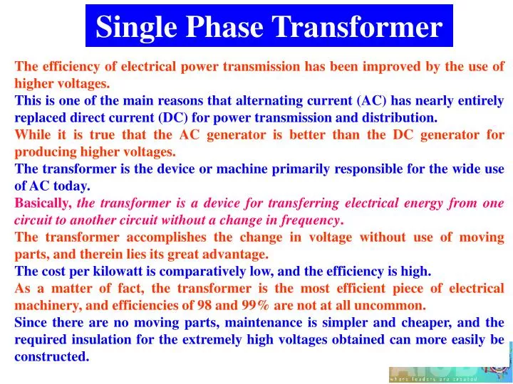
Single Phase Transformer The efficiency of electrical power transmission has been improved by the use of higher voltages. This is one of the main reasons that alternating current (AC) has nearly entirely replaced direct current (DC) for power transmission and distribution. While it is true that the AC generator is better than the DC generator for producing higher voltages. The transformer is the device or machine primarily responsible for the wide use of AC today. Basically, the transformer is a device for transferring electrical energy from one circuit to another circuit without a change in frequency. The transformer accomplishes the change in voltage without use of moving parts, and therein lies its great advantage. The cost per kilowatt is comparatively low, and the efficiency is high. As a matter of fact, the transformer is the most efficient piece of electrical machinery, and efficiencies of 98 and 99% are not at all uncommon. Since there are no moving parts, maintenance is simpler and cheaper, and the required insulation for the extremely high voltages obtained can more easily be constructed.
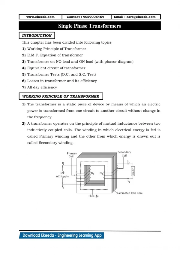
Working Principle of a Transformer A transformer is a static (or stationary) piece of apparatus by means of which electrical power in one circuit is transformed into electric power of the same frequency in another circuit. It can raise (step up) or lower (step down) the voltage in a circuit but with a corresponding decrease or increase in current. Physically, a transformer is mutual induction between two circuits linked by a common magnetic flux. It consists of two inductive coils which are electrically separated but magnetically linked through a path of low reluctance (Fig. 32.1). The two coils possess high mutual inductance. If one coil is connected to a source of AC voltage, an AC flux is set up in the laminated core, most of which is linked with the other coil in which it produce mutually induced emf (according to the faraday’s law of electromagnetic induction e=Mdi/dt).
If the second coil circuit is closed, a current flows in it and so electric energy is transferred (entirely magnetically) from the first coil to the second coil. The first coil, in which electrical energy is fed from the AC supply main, is called primary winding and the other from which energy is drawn out, is called secondary winding. In brief, a transformer is a device that 1. transfers electrical power from one circuit to another 2. it does so without a change of frequency 3. it accomplishes this by electromagnetic induction and 4. where the two electric circuits are in mutual inductive influence of each other.
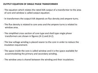
Transformer Construction Constructionally, the transformers are two general types. The two types are known as: Core-type, and Shell-type. In the so called core-type transformers, the windings surround a considerable part of the core(as shown schematically in Fig. 30.3a) whereas in shell type transformers, the core surrounds a considerable portion of the windings(as shown schematically in Fig. 30.3b). For the core type transformers, the primary and secondary winding are located on the opposite legs (or limbs) of the core, but in actual construction, these are always interleaved to reduce leakage flux. As shown in Fig. 32.4, half the primary and half the secondary winding have been placed side by side or concentrically on each limb, not primary on one limb (or leg) and the secondary on the other.
In both core and shell-type transformers, the individual laminations are cut in the form of long strips of L’s, E’s and I’s as shown in Fig. 32.5. The assembly of the compete core for the two types of transformer is shown in Fig. 35.6 and Fig 32.7. In order to avoid high reluctance at the joints where the laminations are butted against each other, the alternate layer are stacked differently to eliminate these joints.
Core-type Transformers In small size core-type transformers, a simple rectangular core is used with cylindrical coils which are either circular or rectangular in form. But for large-size core-type transformers, round or circular cylindrical coils are used. The core is made up of silicon-steel laminations which are either rectangular or L-shaped. With the coils wound on the two legs, the appearance is that of Fig. 14.20.
In order to provide maximum linkage between the windings, the group of each leg is made up of both high-tension and low-tension coils. This may be seen in Fig. 14.21, where a cross-sectional cut is taken across the legs of the core. By placing the high-voltage winding around the low-voltage winding, only one layer of high voltage insulation is required. If the high-voltage coils were adjacent to the core, an additional high voltage insulation layer would be necessary between the coils and the iron core. Thus the arrangement of high-voltage winding around the low-voltage winding reduces the cost of insulation.
Shell-type Transformers As can be seen in Fig. 14.22, the iron almost entirely surrounds the copper in the shell-type construction. The core is made up of E-shaped or F-shaped laminations which are stacked to give a rectangular figure eight. All the windings are placed on the center leg, and in order to reduce leakage, each high-side coil is adjacent to a low-side coil. The coils actually occupy the entire space of both windows, are flat in shape, and are usually constructed of strip copper. Again to reduce the amount of high-voltage insulation required, the low-voltage coils are placed adjacent to the iron core.
Comparison Between Core-type and Shell-type Transformers In the core-type, the magnetic-circuit path is longer, than in the shell-type transformer. In the core-type, the average length per turns is shorter, than in the shell-type transformer. High voltage coil insulation is more easily and economically in the core-type transformer, and therefore its use is often favored for high-voltage low and medium-capacity circuits. For multi-winding design, shell-type construction is preferred by many manufacturers rather than core-type.
In order to obtain circular coils that are used are easier to wound and provide more mechanical strength, especially when short circuit occur, the core of transformer is made by different sizes of laminations. Laminations are used to minimized the eddy current loss. This type of design is called cruciform type as shown in Fig. 14.23. In order to obtain a shorter magnetic circuit and a shorter average length of turn per coils a special type design of core for shell type is shown in Fig. 14.24. This type of design is called distributed shell-type transformer. The distributed core has four returns legs for the magnetic field i.e. there are two more legs at right angles to the original ones. The additional advantage of this type of design is that it makes for a more compact transformer per KVA of capacity.
Transformers are generally housed in tightly-fitted sheet-metal; tanks filled with special insulating oil. This oil has been highly developed and its function is two fold. By circulation, it not only keeps the coils reasonably cool, but also provides the transformer with additional insulation not obtainable when the transformer is left in the air. Another mean of classifying the transformer is according to the type of cooling employed. The following types are in common use: (a) oil-filled self-cooled, (b) oil-filled water cooled, and (c) air-blast type
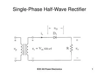
Elementary Theory of an Ideal Transformer An ideal transformer is one which has no losses i.e. its winding have no ohmic resistance, there is no magnetic leakage and hence which has no I2R and core losses. Consider an ideal transformer as shown in Fig. 32.13(a) whose secondary is open and whose primary is connected to sinusoidal alternating voltage V1. This potential difference causes an alternating current to flow in the primary. The function of this current is merely to magnetize the core; it is small in magnitude and legs V1 by 90o. This alternating current Im produces an alternating flux which is, at all times, proportional to the current and hence, is in phase with it.
This changing flux is linked both with the primary and the secondary windings. Therefore, it produces self-induced emf in the primary. This self-induced emfE1 is, at every instant, equal to and in opposition to V1. It is also known as counter emf or back emf of the primary. Similarly, there is produced in the secondary an induced emf E2 which is known as mutually induced emf. The instantaneous values of applied voltage, induced emfs, flux, and magnetizing current are shown by sinusoidal waves in Fig. 32.13 (b). Fig. 32.13(c) shows the vectorial representation of the effective values of the above quantities.
So average rate of change of flux= EMF Equation of a Transformer Let, N1 = No. of turns in primary N2 = No of turns in secondary m = maximum flux in core in webers =BmA f = frequency of AC input in Hz As shown in Fig. 32.14, flux increases from its zero value to maximum value m in one quarter of the cycle i.e. in (1/4f) second . Now rate of change of flux per turn means induced emf in volts. So average emf turn =4fm volt If flux varies sinusoidally, then rms value of induced emf is obtained by multiplying the average value with form factor. So rms value of emf/turn =1.11 4fm= 4.44fmvolt
It is seen from (i) and (ii) that Now rms value of the induced emf in the whole of primary winding = (induced emf/turn)(No. of primary turns) Similarly, rms value of the induced emf in the secondary is, It means that emf turns is the same in both the primary and secondary windings. In an ideal transformer on no load V1=E1 and V2=E2, where V2 is the secondary terminal voltage.
From above equation, we get, Voltage Transformation Ratio (K) This constant K is known as voltage transformation ratio. if N2>N1 i.e. K>1, then trans former is called step-up transformer. if N2<N1 i.e. K<1, then trans former is called step-down transformer. Again for an ideal transformer, Input VA = output VA Hence, currents are in inverse ratio of the voltage transformation ratio.
Transformer with Losses but no Magnetic Leakage We will consider two cases: (i) when such a transformer is on no-load, and (ii) When it is loaded. Transformer on No-Load The core losses and copper losses are neglected in the case of ideal transformer. But in practical conditions, when an actual transformer is put on load, there is iron loss in the core and copper loss in the windings (both primary and secondary) and these losses are not entirely negligible. The primary input under no-load (secondary side open) condition has to supply (i) iron losses in the core (hysteresis loss and eddy current loss) and (ii) a very small amount of copper loss in primary. No-load input power: W0=V1I0cos0 where, cos0 is primary power factor under no-load conditions.
Obviously, I0 is the vector sum of Iw and Im, hence, No-load condition of an actual transformer is shown vectorially in Fig. 32.16. As seen from Fig. 30.16, primary current I0 has two components: 1. one in phase with V1. This is known as active or working or iron loss component Iw because it mainly supplies the iron loss plus small quantity of primary Cu loss. 2. The other component is in quadrature with V1 and is known as magnetizing component Im because its function is to sustain the alternating flux in the core. It is wattles. The no-load primary current I0 is very small as compared to the full-load primary current. As I0 is very small, the no-load primary Cu loss is negligibly small which means that no-load primary input is practically equal to the iron loss in the transformer. Since the core-loss is responsible for shift in the current vector, angle 0 is known as hysteresis angle of advance.
The no-load current I0 is simulated by pure inductance X0 taking the magnetizing component Im and non-inductive resistance R0 taking the working component Iw connected in parallel across the primary circuit as shown in the following Fig.1. The value of X0=E1/Im and of R0=E1/Iw.
Fig. 32. 17(a) Transformer without load Fig. 32.17 (b) Transformer on load Transformer on Load It has already seen that at no load condition only current I0 flows in the circuit as shown in Fig. 32.17(a). This current sets up the flux . When the secondary is loaded, the secondary current I2 is set up. The magnitude and phase of I2 with respect to V2 determined by the characteristics of the load. The secondary current sets up its own mmf (=N2I2) and hence its on flux 2 which is in opposition to the main primary flux which is due to I0 as shown in Fig. 32.17(b). The secondary ampere-turns N2I2 are known as demagnetizing amp-turns. The opposing secondary flux 2 weakens the primary flux , hence primary back emf E1 tends to be reduced.
Fig. 32.17(d) Fig. 32.17(c) For a moment V1 gains upper hand over E1 and hence causes more current to flow in primary. Let the additional primary current be I2’ as shown in Fig. 32.17(c). It is known as load component of primary current. This current is anti-phase with I2 . The additional primary mmf N1I2’ sets up its own flux 2’, which is in opposition to 2 (but is in the same direction as ) and is equal to it in magnitude. Hence the two cancel each other out as shown in Fig. 32.17(d). So, we find that the magnetic effects of secondary current I2 are immediately neutralized by the additional primary current I2’, which is brought into existence exactly at the same instant as I2. Hence, whatever the load conditions, the net flux passing through the core is approximately the same as at no-load.
Fig. 32.17 An important deduction is that due to the constancy of core flux at all loads; the core loss is also practically the same under all load conditions. When transformer is on load, the primary winding has two currents in it; one is I0 and the other I2’ is which is anti-phase with I2 and K times in magnitude (i.e. I2’= I2K). The total primary current is the vector sum of I0 and I2’.
In Fig. 32.8 are shown the vector diagrams for a load transformer when load is non-inductive and when it is inductive. Voltage transformation ratio of unity is assumed so that primary vectors are equal to the secondary vectors. With reference to Fig. 30.18(a), I2 is secondary current in phase with E2. It causes primary current I2’ which is anti-phase with it and equal to it in magnitude. Total primary current I1 is the vector sum of I0 and I2’ and lags behind V1 by an angle 1. In Fig. 30.18(b) vectors are drawn for an inductive load. Here, I2 lags E2 (actually V2) by 2. Current I2’ is again in anti-phase with I2 and equal to it in magnitude. As before, I1 is the vector sum of I2’ and I0 and lags behind V1 by 1.
In Fig. 32.8 are shown the vector diagrams for a load transformer when load is non-inductive and when it is inductive. Voltage transformation ratio of unity is assumed so that primary vectors are equal to the secondary vectors. With reference to Fig. 30.18(a), I2 is secondary current in phase with E2. It causes primary current I2’ which is anti-phase with it and equal to it in magnitude. Total primary current I1 is the vector sum of I0 and I2’ and lags behind V1 by an angle 1. In Fig. 30.18(b) vectors are drawn for an inductive load. Here, I2 lags E2 (actually V2) by 2. Current I2’ is again in anti-phase with I2 and equal to it in magnitude. As before, I1 is the vector sum of I2’ and I0 and lags behind V1 by 1.
Transformer with Winding Resistance but No Magnetic Leakage An ideal transformer was supposed to possess no resistance, but in an actual transformer, there is always present some resistance of the primary and secondary windings as shown in Fig. 32.23. Due to this resistance, there is some voltage drop in the two windings. The result is that: 1. The secondary terminal voltage V2 is vectorially less than the secondary induced emf E2 by an amount I2R2 where R2 is the resistance of the secondary winding. Hence V2 is equal to the vector difference of E2 and resistive voltage drop I2R2. V2=E2-I2R2 vector difference 2. Similarly, primary induced emf E1 is equal to the vector difference of V1 and I1R1 where R1 is the resistance of the primary winding. E1=V1-I1R1 vector difference
Magnetic Leakage In the case of ideal transformer it has been assumed that all the flux linked with primary winding also links the secondary winding. But in practice, all flux linked with primary does not link the secondary but part of it i.e. completes its magnetic circuit by passing through air rather than around the core, as shown in Fig. 32.26. This flux is known as primary leakage flux and is proportional to the primary ampere-turns alone because the secondary turns do not link the magnetic circuit of L1. This flux L1, which is in time phase with I1, induces an emf eL1 in primary but none in secondary. Similarly, secondary part sets up leakage flux L2 which linked with secondary winding alone (and not with primary turns). This flux L2, which is in time phase with I2, produces a self-induced emf eL2 in secondary (but none in primary).
At no-load and light loads, the primary and secondary ampere-turns are small hence leakage fluxes are negligible. But when load is increased, both primary and secondary windings carry huge currents. The effect of induced emf due to the leakage flux is equivalent to a small inductive coil in series with each winding such that voltage drop in each series coil is equal to that produced by leakage flux as shown in Fig. 32.27where X1=eL1/I1 and X2=eL2/I2. The terms X1 and X2 are known as primary and secondary leakage reactances. Following few points should be kept in mind: 1. The leakage flux links one or the other winding but not both, hence it in no way contributes to the transfer of energy from the primary to secondary winding. 2. The primary voltage V1 will have to supply reactive drop I1X1 in addition to I1R1. Similarly, E2 will have to supply reactive drop I2X2 in addition to I2R2.
Transformer with Resistance and Leakage Reactance In Fig. 32.28 as shown the primary and secondary windings of a transformer with reactances taken out of the windings. The primary impedance and voltage equations are given by Similarly, secondary impedance and voltage equations are given by
The vector diagram for such a transformer for different kinds of loads is shown in Fig. 32.29. In these diagrams, vectors for resistive drops are drawn parallel to current vectors whereas reactive drops are perpendicular to the current vectors. In the case of resistive load, the secondary voltage V2 and I2 are in phase. In the case of inductive load, the secondary voltage I2 legs V2 by an angle 2. In the case of inductive load, the secondary voltage I2 leads V2 by an angle 2. The angle 1 between V1 and I1 gives the power factor angle of the transformer.
Similarly, equivalent primary resistance as referred to secondary is Equivalent Resistance, Reactance and Impedance The resistances and reactance of the two windings of a transformer can be transferred to any one of the tow windings. The advantage of concentrating both resistances and reactances in one winding is that it makes calculations very simple and easy because one has then to work in one winding only. It will be provided that the resistance R2, X2, in secondary is equivalent to R2/K2, X2/K2 in primary. The value R2/K2, X2/K2 will be denoted by R2’, X2’ the equivalent secondary resistance as referred to primary. The power loss of resistance R2 in secondary is= I22R2. The power loss of resistance R2’ when R2 is referred to in secondary is= I12R2’. Equating the above two power, we obtain
Similarly, the leakage reactances can also be transferred from one winding to the other in the same way as resistance. Thus Total or effective resistance and reactance of the transformer as referred to primary is Similarly total or effective resistance of the transformer as referred to secondary is
Total or effective impedance of the transformer as referred to primary is As shown in Fig. 32.30(a) Similarly total or effective impedance of the transformer as referred to secondary is As shown in Fig. 32.30(b)
Equivalent Circuit The transformer shown in Fig. 30.37(a) can be resolved into an equivalent circuit in as shown in Fig. 30.37 (b). To make transformer calculation simpler, it is preferable to transfer voltage, current and impedance either to the primary or to the secondary. The primary equivalent of the secondary induced voltage is E2’=E2/K=E1. Similarly, primary equivalent of the secondary terminal or output voltage is V2’=V2/K. Primary equivalent of the secondary current is I2’=I2K. For transferring secondary impedance to primary, K2 is used.
R2’= R2/K2; X2’= X2/K2 ; ZL’= ZL/K2 ; E2’=E2/K=E1. The secondary circuit is shown in Fig. 30.38(a) and its equivalent primary values are shown in Fig. 30.38(b). The total equivalent circuit of the transformer is obtained by adding in the primary impedance as shown in Fig. 32.39. This is known as the exact equivalent circuit but it presents a somewhat harder circuit problem to solve.
A simplification can be made by transferring the exciting circuit across the terminal as in Fig. 32.40 or in Fig. 32.41 (a). Further simplification may be achieved by omitting I0 altogether as shown in Fig. 32.41(b).
From Fig. 32.39, it is found that total impedance between the input terminal is Zm is called impedance of the exciting circuit. The input voltage can be given by
Example 32.1 The maximum flux density in the core of a 250/3000 volts, 50 Hz single phase transformer is 1.2 Wb/m2. If the emf per turn is 8 volt, determine (i) primary and secondary turns, and (ii) area of the core. Solution: (i) E1=N1induced emf/turn; So N1= E1/(induced emf/turn)= 250/8=32 and N2= E2/(induced emf/turn)= 3000/8=375 (ii) We may use
Example 32.3 A single-phase transformer has 400 primary and 1000 secondary turns. The net cross sectional area of the core is 60 cm2. If the primary winding be connected to a 50 Hz supply at 520 V, calculate (i) the peak value of the flux density in the core, and (ii) the voltage induced in the secondary winding. Solution:
Example 32.4 A 25 KVA transformer has 500 turns on the primary and 50 turns on the secondary winding. The primary is connected to 3000V, 50 Hz supply. Find the full-load primary and secondary currents, the secondary emf and the maximum flux in the core. Neglect leakage drops and no-load primary current. Solution: Now, full load I1=2500/3000=8.33 A. Full load I2=I1/K=108.33=83.3 A EMF per turn on primary side= 3000/500= 6 V So, secondary emf= 650= 300 V
Example 32.11 A single phase transformer has 1000 turns on the primary and 200 turns on the secondary. The no load current is 3 A at a pf 0.2 lagging. Calculate the primary current and pf when the secondary current is 280 A at a pf of 0.8 lagging. Solution: V2 is taken as reference cos-1(0.8)=36.87o sin(36.87o)=0.6; K=200/1000=1/5. Thus I1 legs behind the supply by an angle 38.86o.
Transformer Tests The performance of a transformer can be calculated on the basis of equivalent circuit which contains four parameters, the equivalent resistance R01 as referred to primary (or secondary R02), the equivalent leakage reactance X01 as referred to primary (or reactance in secondary X02), the core loss conductance G0 (or resistance R0) and the magnetizing susceptance B0 (or reactance X0). These constants or parameters can be easily determined by two tests (i) open-circuit test and (ii) short-circuit test Open-Circuit or No-Load Test The purpose of this test is to determine no-load loss or core loss and no-load current I0 which is helpful in finding X0 and R0. Low voltage side connected with normal voltage and frequency and high voltage side is left open. A wattmeter W, voltmeter V and an ammeter A are connected in the low-voltage winding i.e. primary winding in the present case as shown in Fig. 32.43.
The voltage V1 is measured using the voltmeter (V). With normal voltage applied to the primary, normal flux will be set up in the core, hence normal iron losses will occur which are recorded by the wattmeter (W). As the primary no-load current I0 (as measured by ammeter, A) is small, Cu loss is negligibly small in primary and null in secondary. Hence, the wattmeter reading represents practically the core loss under no-load condition (and which is the same for all loads). The no-load vector diagram is shown in Fig. 32.16. If W0 is the wattmeter reading as shown in Fig. 32.43, then Since the current is practically all-exciting current when a transformer is on no-load (i.e. I0=Im) and as the voltage drop in primary leakage impedance is small, hence the exciting admittance Y0(=1/Z0) of the transformer is given by I0=V1Y0 or Y0=I0/V1. The exciting conductance G0 is given by W0=V12G0 or G0(=1/R0)= W0 /V12. The exciting susceptance
Separation of Core Losses The core loss of transformer depends upon the frequency and the maximum flux density when the volume and the thickness of the core lamination are given. The core loss is made up of two parts: (i) Hysteresis loss: Wh=PBmax2f and (ii) Eddy current loss: We=QBmax2f 2 Where, P and Q are constant. The total core loss is given by: Wi=Wh+We= PBmax2f + QBmax2f 2. If we carry out two experiments using two different frequencies but the same maximum flux density, we should be able to find the constants P and Q and hence calculate hysteresis and eddy current losses separately. If the maximum flux can be kept same value then the iron or core losses can be written as follows: Wi=Wh+We= Af +Bf 2; where, A= PBmax2; B= QBmax2. From the measured the core loss in two different frequencies, the constant A and B can be calculated.
Short-Circuit or Impedance Test This is an economical method for determining the following: (i) Equivalent impedance (Z01 or Z02), leakage reactance (X01 or X02) and total resistance (R01 or R02) of the transformer as referred to the winding in which the measuring instruments are placed. (ii) Cu loss at full load. This loss is used in calculating the efficiency of the transformer. (iii) Knowing Z01 or Z02, the total voltage drop in the transformer as referred to primary or secondary can be calculated and hence regulation of the transformer determined. In this test, one winding, usually the low-voltage winding is solidly short-circuited by a thick conductor as shown in Fig. 32.45.
A low-voltage (usually 5 to 10% of normal primary voltage) at correct frequency is applied to the primary and is cautiously increased till full-load currents are flowing both in primary and secondary (as indicated by the respective ammeters). Since the applied voltage is a small percentage of the normal voltage, the mutual flux produced is also a small percentage of its normal value. Hence, core losses are very small with the result that the wattmeter reading represents the full-load Cu loss or I2R loss for the whole transformer i.e. both primary Cu loss and secondary Cu loss.