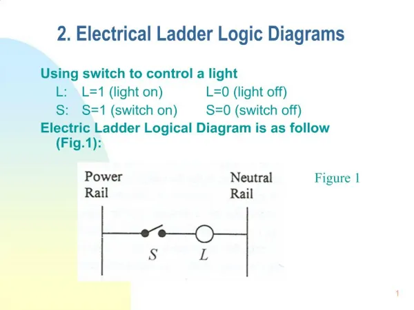
Programming PLCs using LADDER Logic
Programming PLCs using LADDER Logic. Presentation Outline. Review of Ladder Programming Keyence PLC Ladder Builder Example 1: Motor Control Example 2: Drill Control Example 3: Traffic Light. Programming the PLC. Ladder Logic Diagrams Function Block Diagrams Sequential Function Charts


Programming PLCs using LADDER Logic
E N D
Presentation Transcript
Presentation Outline • Review of Ladder Programming • Keyence PLC Ladder Builder • Example 1: Motor Control • Example 2: Drill Control • Example 3: Traffic Light
Programming the PLC • Ladder Logic Diagrams • Function Block Diagrams • Sequential Function Charts • Instruction List • Structured Text • High-Level Language
PLC Scan Cycle Read Inputs Execute Program Update Outputs
Ladder Logic Execution • Rungs of Ladder diagram are solved from Left to right and top to bottom • Branches within rungs are solved top left to bottom right Ladder Rung A D E Left Power Rail Right Power Rail B Branch F G H P S I J K R
Timer Setting Timer Output Input Triggered Basic Ladder Programming
Keyence Ladder Builder • http://www.keyence.com/products/plc.html -> PLC Library • Free evaluation version – up to 50 times • KV -> PLC Series from Keyence
Keyence Ladder Builder • Start -> Programs -> Keyence Applications -> Ladder Builder for KV Sample Ver.
Keyence Ladder Builder Create a new file. Select the KV10 model.
Keyence Ladder Builder Ladder Editor Toolbar
KV-10 Input Relays 0000 – 0005 Output Relays 0500 – 0503 Internal Relays 1000 – 1915 Timers/ Counters T/C 000 – 063 Data Memory DM 0 – 0999 Keyence Ladder Builder Basic Table of I/O
~ ~ Example 1 – Motor Control ~ Stop ~ Start K1 K1 M1 K1 * The overload relay has been omitted in order to simplify the circuit
Example 1 – Motor Control • Stop -> Input Relay 0000 (X000) Normally Closed (NC) • Start -> Input Relay 0001 (X001) Normally Open (NO) • Motor -> Output Relay 0500 (Y050)
Example 1 – Motor Control Ladder Diagram: Stop Start Motor Motor END ENDH
Example 1 – Motor Control Select relay 0001 Add a normally open contact
Example 1 – Motor Control Select relay 0000 Add a normally closed contact
Example 1 – Motor Control Add horizontal connection lines
Example 1 – Motor Control Select relay 0500 Add an output relay
Example 1 – Motor Control Connect the circuit to the right power line
Example 1 – Motor Control Place the cursor below the contact of relay 0001 Select relay 0500 Add a Branch with a NO contact (OR logic)
Example 1 – Motor Control Place the cursor below the NO contact of relay 0500. Type END -> for end of routine . Click OK.
Example 1 – Motor Control Place the cursor below on line 0004. Type ENDH -> for end of program . Click OK.
Example 1 – Motor Control Run the simulator
Example 1 – Motor Control Execute the program for continuous scan
Example 1 – Motor Control Start the motor (turn on and then off the start button) …or double click with the mouse left button Change the status here and Then press Write Current Value…
Example 1 – Motor Control Stop the motor (watch the status of the motor – relay 0500)
Example 1 – Motor Control Stop the simulation and return to the editor
Example 1 – Motor Control Using labels
Example 1 – Motor Control Right click with the mouse button on the device and select Change Label
Example 1 – Motor Control Type the label and press OK (or Enter)
Example 1 – Motor Control Type all labels (save the program – optional) If you use labels you can enter the device by its label (instead of its number)
Example 2 – Drill Control Upper Limit Switch L1 M2 M1 Drill Motor Vertical Motor (up and down) L2 Lower Limit Switch
Example 2 – Drill Control • In the beginning of the drilling cycle the Upper Limit Switch (0001) is closed • The START button (0000) starts the drilling cycle • The drill motor M1 (0500) must start. At the same time, the vertical motor M2 must start to descend the drill (0501) • The drill will stop at the Lower Limit Switch (0002). • At this time, the vertical motor start to ascend the drill (0502). • The drill motor must stop just at the upper position. • Wait for a new drilling cycle
Example 2 – Drill Control Non-retentive contacts:
Example 2 – Drill Control Go to Help -> Instruction Word -> Instructions in Alphabetical Order -> DIFU
Example 2 – Drill Control SET – RESET instructions
Example 2 – Drill Control Go to Help -> Instruction Word -> Instructions in Alphabetical Order -> SET (RES)
Example 2 – Drill Control Timing diagram: LIMIT1 START MOTOR1 LIMIT2 M2-DOWN M2-UP
Example 3 – Traffic Light • Start the operation with the switch S1 (input 0000) • The red signal must be ON for 5 seconds (output 0500) • The green signal must be ON for 8 seconds (output 0501) • The yellow signal must be ON for 3 seconds (output 0502) • The cycle must continues until the switch S1 is released
Example 3 – Traffic Light Go to Help -> Instruction Word -> Instructions in Alphabetical Order -> TMR
Example 3 – Traffic Light Place the cursor at the position you want to add a Timer. Then, double click with the mouse left button and select Instruction -> TMR
Example 3 – Traffic Light Define the Timer number and the Preset value. Timer number Preset value