Download
1 / 53
530 likes | 937 Views
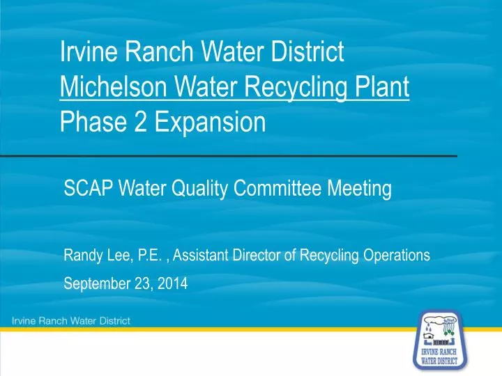
Irvine Ranch Water District Michelson Water Recycling Plant Phase 2 Expansion. SCAP Water Quality Committee Meeting. Randy Lee, P.E. , Assistant Director of Recycling Operations September 23, 2014. Presentation Overview. IRWD Background MWRP Existing Processes Overview

E N D
Irvine Ranch Water DistrictMichelson Water Recycling PlantPhase 2 Expansion SCAP Water Quality Committee Meeting Randy Lee, P.E. , Assistant Director of Recycling Operations September 23, 2014
Presentation Overview • IRWD Background • MWRP Existing Processes Overview • MWRP Phase II Expansion • Biosolids Project Status Update
About the Irvine Ranch Water District • Water, Wastewater, Water Recycling, and Urban Runoff • California Special District governed by a publicly-elected Board • IRWD customer base: • Residential population: 330,000 • Daytime population: >500,000 • Service connections: 102,380 • IRWD service area: • 181 square miles (20% of Orange County) • All or part of six cities and unincorporated county: • Irvine • Tustin • Orange • Lake Forest • Newport Beach • Costa Mesa
Phase 2 Expansion Project ASCE OC Water Treatment Project of the Year - 2013
Michelson Water Recycling Plant • Produces 18 MGD of Title 22 recycled water. • Phase 2 Expansionincreases capacity to 28 MGD. • Scheduled completion June 2014.
Michelson Water Recycling Plant Treatment Process Prior to Expansion FLOW EQUALIZATION BASINS DUAL MEDIA FILTERS PRIMARY SEDIMENTATION TANKS SECONDARY SEDIMENTATION TANKS CHLORINE CONTACT TANKS ACTIVATED SLUDGE BASINS NORTH IRVINE INTERCEPTOR INFLUENT GRINDERS RECYCLED WATER CUSTOMERS SOUTH IRVINE INTERCEPTOR OCSD
Phase 2 Overall Process Train FLOW EQUALIZATION BASINS DUAL MEDIA FILTERS SECONDARY SEDIMENTATION TANKS CHLORINE CONTACT TANKS ACTIVATED SLUDGE BASINS RW CUST. HIGH RATE CLARIFIER PRIMARY SEDIMENTATION TANKS NORTH IRVINE INTERCEPTOR HEADWORKS PRIMARY EFFLUENT PUMP STATION SOUTH IRVINE INTERCEPTOR MEMBRANE BIOREACTOR UV DISINFECTION OCSD
Phase 2 Expansion Overview NEW TREATMENT FACILITIES MODIFIED EXISTING TREATMENT FACILITIES FLOW EQUALIZATION BASINS NEW CHEMICAL FACILITIES NEW ELECTRICAL FACILITIES EXISTING BLOWER ROOM HIGH RATE CLARIFIER MEMBRANE BIOREACTOR UV DISINFECTION PEPS SPENT BACKWASH TANK SPENT BACKWASH TANK EXISTING PSTs NEW PSTs HEADWORKS CHLORINE CONTACT TANK ` EFFLUENT PUMPS
Membrane Bioreactor ANOXIC ZONE DE-OX ZONE BLOWER ROOM AERATION BASIN PERMEATE PUMP ROOM FINE SCREENS ML P.S. MEMBRANE TANKS RAS BOX RAS CHANNEL AERATION BASIN ANOXIC ZONE DE-OX ZONE DIP TANK B.P. TANK
MBR Process Flow 30 MGD 5 MGD 10 MGD 5 MGD 10 MGD 30 MGD
New Phase 2 Buildings Membrane Bioreactor Headworks High Rate Clarifier Electrical Bldg.
Phase 2 Construction Cost • Treatment Process $83 Million • Floodwall $ 5 Million • Overall Construction Cost: $88 Million • Change Orders: $ 4 Million 4.5% • Total $92 Million • Construction Management $14 Million 15%
Biosolids & Energy Recovery Project • Beneficially reuse Biosolids and Biogas produced during the treatment process. • Manage residuals (Biosolids) at reduced costs to IRWD’s customers. • Construct project to meet IRWD’s future Biosolids handling needs. • Minimize environmental impacts:Drying and pelletizing reduces export truck loads by factor of four. • Reduces greenhouse gas effects by beneficially using pellets locally as a fertilizer or e-fuel. • Project Objectives
Biosolids & Energy Recovery Project • IRWD to construct facilities at MWRP for: • Biosolids digestion, dewatering and drying • Biogas management and energy recovery • Odor control systems • IRWD would no longer export solids to Orange County Sanitation District (OCSD). • Project would also accept Biosolids trucked in from IRWD’s Los Alisos Water Recycling Plant (LAWRP). • Project Description
Biosolids Facilities Site Location MWRP Biosolids and Energy Recovery Facilities
Simplified Process Schematic DIGESTER GAS CLEANING MICROTURBINES BIOGAS ELECTRICITY EXISTING PRIMARY CLARIFIER FATS, OILS & GREASE DEWATERING CENTRIFUGE PELLET STORAGE & LOADOUT THICKENINGCENTRIFUGE ROTARYDRUMDRYER PS EXISTING SECONDARY CLARIFIER DIGESTED SLUDGE STORAGE ACID-METHANE PHASE ANAEROBICDIGESTION THICKENINGCENTRIFUGE CLASS A PELLET HAUL CAKE STORAGE & LOADOUT WAS TO LIQUID TREATMENT RECYCLED WATER CENTRATETREATMENT CLASS BCAKE HAUL (BACKUP)
Heat Drying System Furnace Venturi Scrubber GasRecirculation Pellet Cooler Triple Pass Drying Drum Furnace Pneumatic Transporter Condenser ID Fan To Storage Silos Cake from dewatering Atmosphere Cake Bin Recycle Bin RTO Mixer Baghouse Preseparator
Heat Drying System • Produces a pellet suitable for local beneficial reuse • Nitrogen for fertilizer • Btu content for e-fuel • Dryers in CA: • Encina (Carlsbad) • Sacramento • Corona
Digestion Facilities Egg-Shaped Digesters Sludge Holding Tanks Digester Control Bldg. Acid Phase Digesters FOG Foodwaste Receiving. 36
Biosolids Handling Building Dryer and Odor Control Discharge Stacks Polymer Storage Solids Receiving Pellet Loadout
Biosolids Handling Building Dryer Area Centrifuge Area Polymer Storage Centrate Treatment 38
Biogas Storage • Biogas Treatment & Microturbines Biogas Conditioning Microturbines
Centrifuge Room Thickening Centrifuges Dewatering Centrifuges 40
Dryer System – Lower Level Pellet Screen Dryer Drum 41
Dryer System – Upper Level Solids/Off Gas Separation Recycle Bin Pellet Mixer Dryer Drum 42
Pile Installation – Digester Area • Construction Photos • Completed: • Construction of structure and
Pile Installation – Basement of Solids Handling Building • Construction Photos
Installation of Piles in Methane Digester Area • May 2014 Quarterly Report
Installation of Piles in Solids Handling Facility • May 2014 Quarterly Report