Download
1 / 22
220 likes | 875 Views
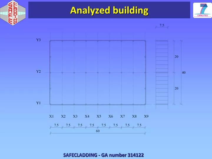
Analyzed building. Four layouts of panel to structure connections. Numerical model of panels. Panels: Elastic response, Unlimited strength Connections with beams: – Unlimited strength. Roof beams. Semi-rigid/rigid diaphragm. Flexible diaphragm. Roof T beam. Roof TT beam.

E N D
Numerical model ofpanels Panels: Elastic response, Unlimited strength Connections with beams: – Unlimited strength
Roofbeams Semi-rigid/rigid diaphragm Flexible diaphragm Roof T beam Roof TT beam
Threetypes of analysis • Modal analysis • Nonlinear static pushover analysis (N2 method; PGA = 0.18g, 0.36g and 0.6 g) • Nonlinear response history analysis (PGA = 0.18, 0.36 and 0.6 g)
Response – Layouts I & II • As an assemblage of cantilever columns – the panels were isolated from main structural system • In the case of rigid and semi rigid diaphragm • In both cases roof beams acted as a rigid diaphragm • Same response in longitudinal and transverse direction • In the case of flexible diaphragm • Response in longitudinal and transverse direction was different
Fundamentalmodes – Layouts I&II Semi-rigid/rigid diaphragm T1 = 1.19 sec: transverse dire. T2 = 1.16 sec: longitudinal dire. Flexible diaphragm T1 = 1.31 sec: transverse dire. T2 = 1.23 sec: longitudinal dire.
Pushoveranalysis – Layouts I&IISemi-rigid (rigid) diaphragm Maximum displacement at 0,6g was 27 cm (good correlation with NRHA) Very limited yielding, even at 0,6g PGA = 0.36 g PGA = 0.60 g
NRHA – Layouts I&IISemi-rigid (rigid) diaphragm Nonlinear response history analysis PGA = 0.6 g
Limited yielding ofcolumnsLayouts I&II Design stiffness42850 kN/m Design strength 2171 kN (q = 3) No strength reduction 6513 kN „Actual strength“ 3200 kN „Actual stiffness“ 22000 kN/m „Actual“ pre-yielding stiffness is 25% of the gross cross-section stiffness
Smallinitialstiffness • Normalized axial force less than 0.005 fck • Cracking moment (force) is quite low Equivalent pre-yielding stiffness
Response – Layout III. & IV. Layout III. and IV. responded similarly and considerably different from the layouts I. and II. • considerably stiffer structures, since the panelswere included into the main structural system • no yielding: elastic models, with • unlimited strength of panels and connections
Fundamentalmodes – Layout III Roof beams were not rigid enough to connect very stiff panels as a rigid diaphragm T1 = 0.54 sec: transverse direction T2 = 0.30 sec: longitudinal direction
DisplacementsLayout I versusLayout III III. LayoutPanels included into the main structural system I. Basic – isostatic layout of panel connections
HystereticloopsLayoutI versusLayoutIII III. LayoutPanels included into the main structural system I. Basic – isostatic layout of panel connections
Conclusions – Basiclayouts of panel connections • Due to the large flexibility of the columns the roof beams were stiff enough to respond as a rigid diaphragm. • The response of this building was essentially elastic even at the design seismic intensity of 0.36 g. • Yielding occurred at 2.4 % drift. • Maximum drift of 3.6 % at PGA 0.6g.
Conclusions – Basic layouts of pannel connections • Limited yielding due to three sources of overstrength: • Material overstrength • Pre-yielding stiffness was much smaller then the 1/2 of the gross cross-section stiffness, used in the design • Number of columns was increased
Conclusions – Other layouts of pannel connections • Buildings with layouts III. and IV. , were considerably stiffer than the basic building with isostaticconnections. • Maximum drift 2.3% at PGA = 0.6 g. • Roof beams could not connect the panels and columns as infinitely rigid diaphragms. • The strength of the panels was not limited, neither the strength of the connections. • The base shear was considerably larger than in the structure with isostatic connections. • In further studies these strengths should be modelled more realistically