Download
1 / 16
170 likes | 408 Views
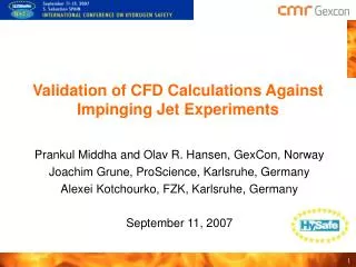
MODELLING OF HYDROGEN JET FIRES USING CFD. Deiveegan Muthusamy 1 , Olav R. Hansen 1 , Prankul Middha 1 , Mark Royle 2 and Deborah Willoughby 2 1 GexCon, P.O.Box 6015, Bergen, NO-5892, Norway 2 HSL/HSE, Harpur Hill, Buxton , Derbyshire SK17 9JN, United Kingdom. BACKGROUND FLACS-FIRE.

E N D
MODELLING OF HYDROGEN JET FIRES USING CFD Deiveegan Muthusamy1, Olav R. Hansen1, Prankul Middha1, Mark Royle2 and Deborah Willoughby2 1GexCon, P.O.Box 6015, Bergen, NO-5892, Norway 2HSL/HSE, Harpur Hill, Buxton, Derbyshire SK17 9JN, United Kingdom
BACKGROUND FLACS-FIRE • FLACS is a leadingtoolwithin offshore oil and gas • Used in most oil and gas explosion/blast studies • Preferredtool for many types ofdispersion studies • Leadingtool for hydrogen safety (applicability & validation) • GexCon wants to add fire functionality • More completetool for risk & consequence studies • Offshore installation standards: Escalation from accidentalloads < 10-4 per year • NORSOK Z-013 (2010) and ISO 19901-3 (2010) • Combinedprobabilistic fire and explosionstudywanted by oil companies
2008 FLACS-FIRE beta-release • Model to simulate jet-fires • Modifiedcombustionmodels for non-premixed • Eddy dissipationconcept (EDC) used by FLUENT, KFX, CFX • Mixed is burnt (MIB) used in FDS • Sootmodelsdeveloped • Formationoxidationmodel (FOM) used in FLUENT, KFX, CFX • Fixedconversionfactor (FCM) used in FDS • Radiationmodel • 6-flux model (correct heat loss, butwrongdistribution) • Output parameters • QWALL (heat loads at surfaces) and Qpoint and QDOSE • Small validation report
FLACS-FIRE 2008-2011 • Temporary stop in development 2008 • Main resources re-allocated to betterpaidactivities • Somevalidation and evaluationworkperformed • FLACS-FIRE beta-versiontaken back • Conclusionsofevaluation • Flameshapes and fire dynamics wellsimulated • Radiationpatternverywrong (alongaxes) • Model muchtooslow (explosion ~1s, fire ~1000 s) • Need for improved output • Joint industryproject 2009-2011 (ExxonMobil, Total, IRSN, Statoil) • Parallelversionof FLACS (~3 times faster with 4 CPUs) • Incompressiblesolver (~10 times faster) • Work on embedded grids (e.g. around jets) ongoing • 2010 => Building up new fire modeling team • Ray-tracing model (DTM) for radiation (optimizationremains) • Validationand methodologydevelopmentongoing • 2012 => JIP on FIRE will start, partners get beta-versions and caninfluencedevelopment FLACS-FIRE simulation Murcia test facility
CURRENT WORK: FLACS-FIRE FOR HYDROGEN • For hydrogen simulationsthefollowingmodelsare used • EDC combustionmodel (adaptivelyactivated for non-premixedflames) • Sootmodel not relevant for hydrogen • DTM (raytracing) radiationmodel used • Simulated HSL jet fire tests (variationof barriers and releaseorifice diameter)
OVERVIEW HSL FIRE EXPERIMENTS • Horizontal jet fire experiments • Three releaseorifices (200 bar & 100 litre) • 3.2mm, 6.4mm and 9.5mm • Three barriers configurations • 90 degree, 60 degree and no barriers (only 9.5mm) • Release at 1.2m height • Ignition2m from release at 800ms • Barriers 2.6m from release location
OVERVIEW HSL FIRE EXPERIMENTS • Results • Overpressures at sensors • Heat flux at sensors
GexCon did not focus on explosionpressures • Guidelines for grid and time step for explosion and fire are different • For thisstudyweoptimized grid and timestep for fire => did not studypressures • Previouslydemonstratedthat FLACS canpredictexploding hydrogen jets well FZK (KIT) ignited jets Sandia/SRI barrier tests Sandia/SRI tunnel tests
Simulationsetup • Guidelines for FLACS-FIRE (grid / time step) as for FLACS-DISPERSION • Grid refinementnearjet (Acv < Ajet < 1.25 Acv) • Refinementwhere gradients areexpected • Maximum grid aspect ratio of 5 near jet • Time step: CFLV max 2 • 100.000 to 200.000 grid cells • Transientrelease rates (one tank insteadoftwo?)
Results • Exampleofflametemperaturedistribution • 3.2mm (3s) • 6.4mm (2.3s)
Results • Exampleofflametemperaturedistribution • 9.5mm (1.4 to 1.8s) • During theworkwe «struggled» to getthe proper heatfluxesas output • Weidentifiederrors in theradiationroutines • Convective heat from jet-flameimpingement not radiation, is reported in paper
COMPARISON 9.5mm VS VIDEO Photo of jet-flameindicatesdownwards angle (possiblyillusiondue to cameraposition) Reactionzonecorrespondswithbright region 1500 K contourwith visible flamelength? T > 1300 K zone Reactionzone
COMPARISON 9.5mm VS VIDEO Notice: Photo of jet-flameindicatesdownwards angle (could be illusion due to cameraposition) Reactionzonecorrespondswithbright region 1500 K contourwith visible flamelength? Rotated so jet becomeshorizontal T > 1300 K zone Reactionzone
DOUBLE PEAK IN SIMULATION, NOT IN TEST? T > 1300 K zone Double peakseen in simulation, not in photo (?) Rotated so jet becomeshorizontal peak 1 peak 2 Explanation 2: Slowervelocityinto ”peak 1” than ”peak 2” glowing elements or particleswill have quenched in ”peak 1” Explanation 1: first peakoptically ”thin” >40 m/s < 10 m/s
DOUBLE PEAK IN SIMULATION, NOT IN TEST? T > 1500 K zonecorresponds to visible plume? peak 1 peak 2 Double peakalso in test (weakcontoursseen)! Explanation 2: Slowervelocityinto ”peak 1” than ”peak 2” glowing elements or particleswill have quenched in ”peak 1” Explanation 1: first peakoptically ”thin” >40 m/s < 10 m/s
CONCLUSIONS • Due to setuperrors and inaccuraciesthe FLACS-FIRE comparison to HSL tests not accurate • Alsoinfluenced by thefactthat FLACS-FIRE is an unfinishedproduct under development • Still promisingresult and progress seen • Expect prototype version for JIP-members 2012 • Will be commerciallyavailableoncequality is comparable to other FLACS-products (validation and functionality) PredictedradiationkW/m2 (horizontalsurfaces) and flamesimulating jet-fire on oil platform Acknowledgment • Thanks to the research council of Norway for partial support to IEA Task 31 participation