Download
1 / 23
230 likes | 283 Views
This presentation at ICANS XXIII in 2019 covers an overview of the 2MW SNS target, pulse analysis findings, and base material fatigue life analysis methods and results. Details on design modifications, target challenges, and the use of Fe-Safe for evaluating fatigue life and strain reduction needed are discussed, as well as insights on stress response and sub-modeling approaches. The study delves into factors affecting target performance, such as radiation, heat generation, thermal stress, and cavitation effects, providing a comprehensive analysis to enhance operational efficiency and target longevity at the spallation neutron source.

E N D
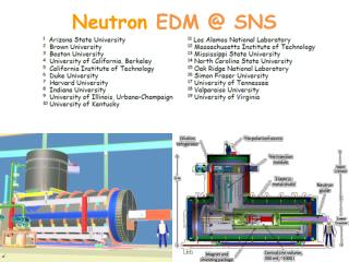
Spallation Neutron Source (SNS) 2 MW Target Life Analysis Justin Mach, Kevin Johns, Sarma Gorti ICANS XXIII, Chattanooga, TN October 14th, 2019
Agenda • 2 MW Target Overview • Brief Review of Pulse Analysis • Base Material Fatigue Life Analysis • Methods • Preliminary Results • Sub-Modeling Approach (for detailed geometry) • Future Work / Summary
TargetOverview Mercury vessel with solid mercury model shown Jet Flow Window Flow
PPUTargetChanges • The PPU target has several major design modifications conceived during the conceptual design phase to improve target performance for 2MW operation • Tapered nose for improved shear flow in corners. Improves pulse mode vulnerability. • Removed center baffle directly in beam path. Taper also improves structural response with baffle removed. • Swirl bubblers implemented for reliable, high gas flow rate injection.
TargetChallenges • Radiation • Materials become brittle, DPA limit, restricts sensor and materials used • Heat • Proton beam generates heat quickly • Mercury vessel cooled by circulating mercury • Thermal stress • Fatigue • Pressure field generated from energy deposition • 60Hz pulse rate pushes targets into high cycle fatigue regime(giga cycle) • Cavitation • Collapsing mercury bubbles create mercury jets which erode vessel walls. • Inner window exhibits worst damaged area, but leaks have occurred elsewhere • Time • 2.5-3 year cycle to see effect of new features Photo Credit: http.eswt.net/cavitation
PeakBeam Pulse Comparison • Fe-Safe is used to evaluate fatigue life of targets • Predicts onset of fatigue damage, does not predict when a failure (leak) occurs • We do not expect to meet fatigue life without gas injection 44% ↑ increase in peak pulse pressure!
Fixed boundary (steel) Pulse Analysis Non-reflecting boundary (Mercury) X-symmetry boundary Initial Pressure Field (mapped from Neutronics analysis)
PulseStress- Center Most Ribs Have Highest Stresses 261 MPa(121 μs) 176 MPa(75 μs) 123 MPa(48 μs) 114 MPa(232 μs) 153 MPa(100 μs) 245 MPa(125 μs) Peak stresses shown at different locations occur at different times 147 MPa(171 μs) 169 MPa(85 μs) 209 MPa(72 μs)
JetFlow Stress Response Most Damaging Run 2 Run 1 300 μs 700 μs Window return Jet flow Window supply Element centroid values are lower than values at the surface nodes
Default fe-safe™ material model algorithm for 316 SS Brown-Miller strain-life equation with critical plane approach
FEA Loading File • Without static loading superimposed on pulse loading • With static loading superimposed on pulse loading • Customizable for other combinations of loading • Static+Thermal+Pulse • Block Repeats • Scaling . . . . . .
Strain reduction needed from gas injection Fe-safe iteratively solves for strength factor that satisfies design life that you specify 32% (E: 45%) (strain reduction needed from gas injection to achieve target life = 270M cycles)
Example results – log10(life) – repeats/cycles/pulses • Banded • No averaging Minimum life =106.802 = 6.3M repeats/cycles/pulses
Example results – strength factor • Banded • No averaging Minimum strength factor = 0.68 → 1 - 0.68 = 0.32 → 32% strain reduction needed to achieve design life (2.7E8)
FatigueCurve is Under Evaluation • ASME curve is conservative relative to data―built in safety factors • Past targets have been run past predicted fatigue damage cycle limit without evidence of damage • J-Parc has done valuable testing on their material and welds with positive results • Desire to test our own material under varying conditions
Hercules: Lowest Life (0.41M) at Inner Jet Flow Rib 270M cycles (1250 hours @ 60Hz) 6M E: 16M 36M 0.1M cycles 0.41M E: 1.1M 4.9M E: 8.9M 52% (E: 45%) (strain reduction needed from gas injection to achieve target life = 270M cycles) 0.1625” 39M E: 36M
Hercules: Lowest Life (6.3M) at Inner Jet Flow Rib 270M cycles (1250 hours @ 60Hz) 9.4M E: 16M 0.1M cycles 49M E: 8.9M 32% (E: 45%) (strain reduction needed from gas injection to achieve target life = 270M cycles) 6.3M E: 1.1M 38M 6.8M E: 36M
Sub-Modeling • Global model: Hercules • No vane dummy bubbler • 5.2M elements • Pulse load map based on Eridanus geometry • Submodel: • 4 unit, 2 vane swirl bubbler • 3.15M elements • Global model displacement output interval = 5e-7 sec. “Driving” element/node set from global model (near surface only) “Driven” node set for submodel (surface only)
Peak stress (142 MPa) at outside corner of vane at ~250 µsec on downstream side • Outside corner at radius end is sharp (stress singularity) • Stress at next frame is 124 MPa on downstream surface of vane fillet in same region
Lowestlife (74M cycles) on sharp corner of vane (stress singularity) Non-singular lowest life is 120M cycles on fillet. 270M 165M 74M 74M Stress singularity 120M Surface finish: Ra ≤ 0.25 µm (10 µin), Kt = 1 (electro-polishing ~ 12-16 µin at best)
Lowest life (39M cycles) on sharp corner of vane (stress singularity) Non-singular lowest life is 64M cycles on fillet. 270M 85M 39M 39M Stress singularity ~50% life reduction 64M Surface finish: 0.6 (24 µin) < Ra ≤ 1.6 µm (64 µin), Kt = 1.06275 (EDM / conventional machining)
Future work • Weld Fatigue Analysis • ASME BPVC Sec. VIII Div. 2 Part 5.5.3 (Fatigue Assessment – Elastic Stress and Equivalent Stresses) – “k-factor” approach based on weld quality • ASME BPVC Sec. VIII Div. 2 Part 5.5.5 (Fatigue Assessment – Elastic Analysis and Structural Stress) • Custom Matlab code • fe-safe™/Verity (Enhanced Nodal Force Method) • Mercury material model improvements • Predict Mercury-Helium (gas injection) response • Predict Mercury cavitation response • Improve correlation with target strain response
Summary • 2MW target design must withstand 44% higher peak pulse pressure • Commercial fatigue analysis tools (fe-safe™) and standard code methods (ASME BPVC) • Evolving design iterations to improve lowest life locations • Sub-modeling for analysis of detailed geometry, e.g. swirl bubbler