Download
1 / 20
200 likes | 928 Views
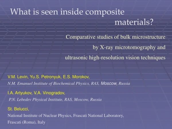
What is seen inside composite materials?. Comparative studies of bulk microstructure by X-ray microtomography and ultrasonic high-resolution vision techniques. V.M. Levin, Yu.S. Petronyuk, E.S. Morokov, N.M. Emanuel Institute of Biochemical Physics, RAS, Moscow, Russia

E N D
What is seen inside composite materials? Comparative studies of bulk microstructure by X-ray microtomography and ultrasonic high-resolution vision techniques V.M. Levin, Yu.S. Petronyuk, E.S. Morokov, N.M. Emanuel Institute of Biochemical Physics, RAS, Moscow,Russia I.A. Artyukov,V.A. Vinogradov, P.N. Lebedev Physical Institute, RAS, Moscow, Russia St. Belucci, National Institute of Nuclear Physics, Frascati National Laboratory, Frascati (Roma), Italy
The mainstream of contemporary material science and engineering - well-organized composite materials for load-carrying construction elements. Main directions of activity: design, manufacture, applications Accompanied tasks: 1. composite microstructure- investigation, inspection and control; 2. fracture micromechanics of composites: - real-timeobservation of fracture and damageprocesses, - revealing physical mechanisms of irreversible structural changes in the material bulk. main topics of the report
Ways for microstructural studies: Destructive techniques: All methods are applied for surface visualization only. Conventional methods – optical microscopy, electron microscopy, probe microscopy, etc They require specimen cutting, surface polishing and treating Non-destructive techniques: X-ray computer microtomography: is based on recovering 2D massive of data on values of the probe X-ray radiation transmitted through a specimen in various direction . high-frequency ultrasonic bulk visualization: impulse acoustic microscopy, laser ultrasound. is based on reception of echo signals resulted from reflection of the probe pulse of focused ultrasound from diverse structural elements within the specimen volume.
linear set of precise photodetectors Computer tomography idea: X-ray absorption in a specimen: I(s,) - X-ray intensity after ray propagation from A to A’ ; I0 – incident intensity of X-ray radiation (x,y) – local coefficient of X-ray absorption (X-ray density). Measured value – integral X-ray absorption along the path AA’: Z-axis 1 2 3 Radon transformation of the measured R(s,) into real (x,y). Saving the receiving data as 2D image of the specimen cross-section at a given z position. probe X-ray radiation Repetition of data acquisition at diverse positions z of restored cross-sections. Compiling the database for 3D imaging/
f = 50 MHz Acoustical objective (lens), (50 – 200)MHz Scanning directions Immersion liquid focal area of the probe beam Focal spot reflected echo pulses probe pulse x Specimen motion (scanning) of the probe beam Impulse acoustic microscopy idea: • Impulse probe signal of focused ultrasound; • Reflection regime; • Time resolution of echo signals coming • from different depth inside the specimen bulk • 1D or 2D probe beam scanning for image formation
Basic regimes for data representation: B T 2L L LT Electronic gate (given by green color) – technique of signal processing for displaying recorded signals as acoustical B- and C-scans. electronic gate Echo pattern- reflected signal oscillogram B-scan - image of a specimen cross-section produced by 1D motion of the probe beam echo pulse C-scan - gray-scale image of an internal layer produced by 2D scanning. The layer position is set by electronic gate. probe pulse scanning direction probe pulse scanning directions probe pulse
1. 3 1 2 2. 3. Ultrasonic microtomography:layer-by-layerimaging of internal microstructure in the specimen bulk Electronic gate positions
Presentation aims: - bulk microstructure imaging in epoxy +carbon nanofillers composites; - bulk microstructure visualization in carbon fiber reinforced composite (CFRC) laminates; - observation of microstructural failure under mechanical loading. Applied techniques: - impulse acoustic microscopy - synchrotron and X-ray microtomography. Instrumentaion: Beijing Synchrotron Radiation Facility (Institute of High Energy Physics, CAS): Resolution : probe beam 20 μm Scanning impulse acoustic microscopeSIАМ-2 (Institute of Biochemical Physics, RAS, 2011): Operation frequency – 50 - 200 MHz Resolution – 15-60 µm Scanning step – 15 µm X-ray microtomograph Skyscan-1074 (P.N. LebedevPhysical Institute, RAS): Resolution : probe beam 23 μm Regimes - 3D visualization (tomography), А, В and С-scans
Microstructure of Nanocarbon – Epoxy Cocomposites Binder:epoxi resin Epicote Resin 828 Nanofillrer: (a). Exfoliated graphite (EG): milled exfoliated graphite, particle sizes – (20 500) µm. (b). Flat micronic graphite (FMG): fine milling and thermal treating of exfoliated graphite. Graphite stacks consisting of 30- 40 graphite atomic layers. Lateral sizes are not larger than 10-15 μm. • (c). Graphite nano-platelets (GNP): • Intercalation PulverizationAdditional milling . • Thickness 10 nm, lateral sizes 1 - 10 m. (d). Multiwall carbon nanotubes (MWCNT): CVD produced carbon multiwall nanotubes, Ø 20 – 40 nm, 5 - 12 m long. Uniform distribution of graphite nanoparticles no elements for acoustic imaging. Only inhomogeneous particle distribution generates acoustical pictures
3D imaging of carbon nanocomposites bulk microstructure Epoxy + 0.75%w GNP, thickness d = 1.56 mm surface subsurface Numerous air-filled particle agglomerates bulk layer bottom
Bulk microstucture of the (epoxy+1.5 w% exfoliated graphite)specimen (thickness d = 1.44 mm) as seen by focused ultrasound, f = 50 MHz, λ = 30 μm synchrotron radiation; probe beam 20 μm
Bulk microstucture of the (epoxy+0.1 w% MWCNT)specimen (thickness d = 1.4 mm) as seen by synchrotron radiation; probe beam 20 μm focused ultrasound, f = 50 MHz, λ = 30 μm
Acoustic contrast as a result of non-uniform distribution of nanotubes Areas of nanotube concentration Individual nanotubes Electron microscopy image Assumed nanotube ditribution
Microstructure of Carbon Fiber Reinforced Composite (CFRC) Laminates
What does the high-frequency focused ultrasound see inside the bulk of reinforced plastics? • fiber orientation, • interply boundaries, • caverns and pores, • adhesion losses at the fiber –matrix interface, • cracks , • wrinkling of individual laminae, resin pocket formation; • defects of prepreg ply or fabric sheet stacking • interplydelaminations, • rupture of fiber bundles and threads
surface wrinkles bottom Topology of the basic structural units in CFRC materials Geometry of ply package as it is seen in B-scans Acoustical images of fiber package in successive layers of the (00/+450/900/-450)4 epoxy-based CFRC laminate. Bright lines parallel to fibers are possile places of adhesion lost between fiber bundles and epoxy matrix X-ray image of fiber package
Fracture processes in CFRC materials
Acoustic imaging of fiber fracture inside the CFRC material bulk Rupture of fiber threads inside a CFRC specimen manufactured by thread winding. Depth of 150-200 µm under the specimen surface Broken individual filaments resulting from the rupture.
Nucleation and dynamics of failures in cross-shaped conjunction of CFRC ribs under growing tensile load depth – 700 µm depth – 200 µm Acoustical images (C-scans) of microstructure at depth of 200 µm (on the left), 700 µm (on the right) (a, b) – initial structure of the conjunction before loading; (c, d) – structure of same areas after tensile loading by 50 kN; (e, f) - after tensile loading by 65 kN 1 – technological defects; 2 – failures initiated by mechanical loading. Ultrasonic operation frequency100 MHz Viewing field – 17 mm 39 mm
Conclusions: The both visualization techniques – X-ray tomography and impulse acoustic microscopy are powerful nondestructive methods of studying the bulk microstructure of composite materials with micron resolution. The techniques make it possible to see all basic microstructural units of composite materials. The techniques allow to reveal all types of structural microdefects caused by technological faults or generated by mechanical loads . The techniques provide unique capability to follow evolution dynamics of structural defects from their nucleation up to transformation into macro-scaled failures. The technique is a unique instrument to establish physical basis for fracture processes in composites.