Download
1 / 25

E N D
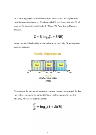
CA (Carrier Aggregation), MIMO (Multi-input Multi-output), and higher-order modulation are introduced in LTE-Advanced Rel 10 to enhance data rate. 5G NR expands this trend, utilizing CA in both FR1 and FR2. According to Shannon Theorem: Larger bandwidth leads to higher channel capacity, that’s why CA technique can augment data rate. Nevertheless, the spectrum is a precious resource. How can we augment the data rate without increasing the bandwidth? So, we define a parameter, spectral efficiency, which is the data rate per Hz. 1 1
In LTE-Advanced, we have two methods to enhance spectral efficiency: MIMO and higher-order modulation. The definition of SISO, SIMO, MISO, and MIMO is as shown below: SIMO is also known as receiving diversity, which is often used to enable a receiver system that receives signals from many independent sources to combat the effects of fading and enhance the sensitivity. For example, if the sensitivity is -97 dBm with a single antenna, the sensitivity would be -100 dBm approximately with two antennas. 2 2
In recent years, almost all cellphones have a diversity receiving antenna for the cellular system. Usually, we put the primary antenna on the bottom side to mitigate SAR (Specific Absorption Rate) issue. Besides, putting the diversity antenna on the top side can enhance the antenna-to-antenna isolation, which is particularly crucial in the CA operation. 3 3
As shown above, this router provides four data streams. Therefore, you can connect and simultaneously transfer data to four smartphones with 1x1 MIMO because each smartphone uses only one stream. Alternatively, you can connect and simultaneously transfer data to two tablets with 2x2 MIMO, to one laptop with 3x3 MIMO and one smartphone with 1x1 SISO or just to one device, if it offers support for 4x4 MIMO. However, that a device with 4x4 MIMO has the benefit of transfer speeds that are a lot faster than one smartphone with 1x1 SISO [3]. The maximum number of streams, denoted by M, is limited by the smaller of the number of antennas at the transmitter or the receiver. For example, in this case below, M is 3, which means there would be 3 simultaneous data streams maximumly. TX Terminal RX Terminal 5 5
According to these formulas, compared to a SISO system, the channel capacity of a MIMO system can be improved M times. Consequently, due to more data streams, MIMO can enhance data rate without widening the bandwidth. Or, we can say, the approach of MIMO improves spectral efficiency. 6 6
Consequently, if we combine the concepts of CA and MIMO, it would be like this: Certainly, the data rate increases dramatically. 7 7
Because the low band is not optimal for 4x4 MIMO due to constraints on antenna size, the bands supporting 4x4 MIMO need to be in one of the following frequency ranges [5]: · Mid-band (MB) · High-band (HB) · Ultra-high-band (UHB; ~3.5 GHz) · 5 GHz range using Licensed Assisted Access (LAA) 8 8
As well as MIMO, another approach to enhance spectral efficiency is higher-order modulation. In LTE-Advanced, the highest order modulation is 256 QAM, which is identical to both FR1 and FR2 of 5G. Symbol rate means how many bits each symbol represents, which is also bits per symbol. 64-QAM means each symbol represents 6 bits, and 256-QAM means each symbol represents 8 bits. Thus, due to higher symbol rate, higher order modulation can enhance data rate. 9 9
Though higher-order modulation can enhance spectral efficiency, yet it increases PAPR as well, as shown above [4]. However, to avoid clipping, back-off is a necessary approach, and higher PAPR leads to more back-off and lower PA efficiency. By the way, the GSM system can operate in saturation zone without clipping since its modulation type is GMSK, which is constant envelope and zero PAPR. 10 10
To put it another way, higher-order modulation suffers from lower efficiency, which may cause the thermal issue. In addition, high PAPR due to intra-band contiguous UL case is inevitable [6]. 11 11
Consequently, if both high order modulation (256-QAM) and intra-band contiguous UL CA are adopted simultaneously, the PAPR would be more significant. To put it another way, the thermal issue may aggravate and enhance self-heating. With broader bandwidth (due to intra-band contiguous UL CA) and more severe self-heating, the memory effect in PAs may become more severe, and asymmetrical ACLR would be more apparent [6]. Frequency drift due to high temperature is a big concern as well, and particularly in the high channel. From TX perspective, the PA post-loss increases, which increases PA output power to achieve the target power, thereby aggravating TX performance. From RX perspective, the sensitivity worsens due to more loss. 12 12
As for inter-band UL CA, we have to deal with the intermodulation issue for (LB- LB) or (MB-MB) combination and harmonic product issue for (LB-MB) combination [6]. For example, B17 3rd order harmonic product may interfere with B4 RX due to poor isolation of trace-to-trace, port-to-port of ASM, and antenna- to-antenna. 13 13
As for B17 RX, 0.5 dB degradation is due to LPF loss. As for B4 RX, 6.8 dB degradation is due to the higher noise floor caused by B17 3rd harmonic product. Although a LPF has been added, yet the B4 RX noise floor still increases. As shown above, perhaps the trace-to-trace isolation is not high enough. The 3rd harmonic product from B17 at B4 received band would be less than -183 dBm/Hz. 14 14
LB PA A LB PA B In terms of harmonic product suppression, both A and B scenarios are identical. Nevertheless, in the B scenario, the loss of LPF is not added to RX path, and in A scenario, the loss of LPF is added to both TX and RX paths. Thus, the B scenario is better. 15 15
TVS (Transient Voltage Suppression) is often added on ASM ANT port path to avoid making ESD damage ASM. Nevertheless, the limited VBR of TVS clips RF signal, which causes distortion and then harmonics may worsen [1]. 16 16
For B17, if 2H noise (about 1400 MHz) exists on PA Vcc path, the 3H product may worsen due to IMD mechanism [1]. Once in a while, an issue is composed of several factors, not a single one, yet PA dominates the whole 3H level. 17 17
Therefore, the PA output impedance should be tuned to high linearity zone to achieve lower harmonics; we have to sacrifice a bit efficiency, though. 18 18
If we take PA as: and take 3H product@PA input as: we can get PA output 3H product as: That is to say, the 3H at PA input contributes to the 3H at PA output as well. Thus, we can add a LPF or notch filter at PA input to suppress 3H product generated from transceiver, thereby lowering 3H product at PA output. 19 19
For IMD3(3rd order intermodulation) calculation [1]: From the formula, we know that either attenuating the two tones or improving the linearity can lower the IMD3. In addition to active devices, passive devices, such as duplexers, also generate IMD products due to nonlinearity. For B1/B3 combination CA, 2B1TX – B3TX = B1RX. That is, both B1 and B3 transmitting signals can generate IMD products falling into B1 received bands, thereby causing the desense issue. 20 20
As shown above, the IMD3 product generated by quadplexer nonlinearity may interfere with B1 RX by quadplexer, ASDiV limited isolation, and limited ANT-to- ANT isolation. Besides, 2B3TX – B1TX = GPS, the IMD3 product may interfere with GPS signal as well by the limited ANT-to-ANT isolation. Regarding inter-band, TDD-TDD CA scenario, if there’s a overlap between TX and RX timing, there would be in-band and cross band isolation. 21 21
As mentioned earlier, passive devices, such as duplexers, can also generate IMD products due to nonlinearity, and this is relevant to high power rating, or power handling capability. Thus, we have to choose high power handling capability when we determine the passive devices, especially for the CA application. If you still wanna use a single antenna without a diplexer, a three-port device is also necessary. You can have two choices [1]: 1. Phase shifter 2. Quadplexer 22 22
For a multiplexer, both in-band and cross-band isolation need to be supported and at least 50 dB. Also, compared to the duplexer, the quadplexer has higher insertion loss. Nevertheless, using the multiplexer reduces the throw count of the band select switch, which can be a significant benefit due to lower switch insertion loss and complexity, and this is especially beneficial to those non-CA bands [7]. 23 23
Therefore, in terms of loss, we have to compare the two scenarios: 1.Quadplexer + ASM with fewer ports 2.Duplexer + diplexer + ASM with more ports And, choose the lower one. 24 24
Reference [1] Carrier Aggregation Discussion [2] 4x4 MIMO Boosts 4G and Gives Consumers a Taste of the Gigabit Experience [3] Simple questions: What is MU-MIMO in WiFi? Do I need it? [4] Energy Efficiency Evaluation of Linear Transmitters for 5G NR Wireless Waveforms [5] The Easy Way to a 1 Gbps RF Front-End on Smartphones, Qorvo [6] ABCs of Carrier Aggregation 25 25