Download
1 / 33
330 likes | 467 Views
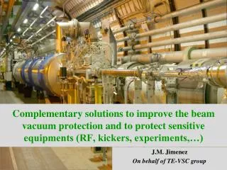
Session 3 - Optimise Interventions and Recovery from Collateral Damages on Cold Sectors Means to limit the collateral damages in the beam vacuum chambers . J.M. Jimenez On behalf of TE-VSC group

E N D
Session 3 - Optimise Interventions and Recovery from Collateral Damages on Cold SectorsMeans to limit the collateral damages in the beam vacuum chambers J.M. Jimenez On behalf of TE-VSC group Thanks to V. Baglin, P. Coly, P. Cruikshank, C. Garion, J. Strait, L. Tavian, R. Veness and R. Van Weelderen for their help
Main Topics • Introduction • Review of the Vacuum Failure modes • Expected consequences • Mitigation solutions • Closing remarks
IntroductionLHC Beam Vacuum Sectorisation • Brief history: Beam Vacuum system has been designed to limit, whenever possible, the impact of small air or helium leaks: welds, seals, feedthroughs, holes in beam screen capillaries, etc. LHC Beam Vacuum Sectorisation • 8 arcs and 8 straight sections • Separation of cold and RT vacuum systems • Create vacuum sectors in long/fragile RT zones • Equipment which need and ex-situ conditioning • At the experimental areas 19th Sept’08 incidentwas not expected
IntroductionRisk Analysis of the LHC cryogenic system (1/4) • Reference document: LHC-project note 177: CourtesyL. Tavian
IntroductionRisk Analysis of the LHC cryogenic system (2/4) CourtesyL. Tavian
IntroductionRisk Analysis of the LHC cryogenic system (3/4) Gravity 3b: Helium is blown out of the machine in confined areas while access to these areas is allowed, under controlled conditions CourtesyL. Tavian
IntroductionRisk Analysis of the LHC cryogenic system (4/4) CourtesyL. Tavian
IntroductionExperience from SM18 String Test & MCI • Following the electrical problemproduced on the String experiment (see LHC-XMS-ER-0002 rev 1.0), no special warning was triggered at the time concerning the large collateral damages that could be created. • MCI is equivalent to a discharge of40 kg/s even in case the M1, M2and M3 lines are damaged simultaneously MCIeq. 40 kg/s 19th Sept’08 incident CourtesyL. Tavian
Introduction19th Sept’08: Damages to the Beam Vacuum Q8R3 V1: rupture disk deformed but not perforated Second % is after removing the 53 magnets of the D-zone Q8R3 V2: rupturedisk blown Q8L4 V1/V2: rupture disk deformed but not perforated
Introduction« As built » situation • Arcs Insulation vacuum • Vacuum barriers (204 m) • Spring relief valve (2 by vacuum subsector eq. DN90) • Safety relief valves (DN200) and/or declamped flanges (DN63 and DN100) • By-pass installed across all vacuum barriers (5 arcs completed/8) • Arc Beam vacuum • Rupture disks (30 mm aperture) available at each arc extremity (~3 km) • No vacuum sectorisation ! • Long straight sections Warm vacuum sectors • Vacuum sector valves (Warm sectors can always be isolated from SAM) • Long straight sections Standalone Magnets (SAM) • Insulation vacuum • Spring relief safety valve • Safety relief valves (DN200) and/or declamped flanges (DN63 and DN100) • Beam vacuum • Rupture disks (30 mm aperture) available at each SAM extremity (max. length in triplets) • Vacuum sector valves at each extremities (isolate from the warm vacuum sector) • Experimental areas • Vacuum sector valves at Q1 (each side) and to isolate the central beam pipes • Pressure relief valve (only in LHCb Velo) • Rupture disks (30 mm aperture) at each extremity of each Experimental area (close to Q1)
IntroductionSituation after the 3-4 Incident • Arcs Insulation vacuum • Vacuum barriers (204 m) • Spring relief valve (2 by vacuum subsector eq. DN90) • Safety relief valves (DN200) and/or declamped flanges (DN63 and DN100) • By-pass installed across all vacuum barriers (5 arcs completed/8) • Arc Beam vacuum • Rupture disks (30 mm aperture) available at each arc extremity (~3 km) • No vacuum sectorisation ! • Long straight sections Warm vacuum sectors • Vacuum sector valves (Warm sectors can always be isolated from SAM) • Long straight sections Standalone Magnets (SAM) • Insulation vacuum • Spring relief safety valve • Safety relief valves (DN200) and/or declamped flanges (DN63 and DN100) • Beam vacuum • Rupture disks (30 mm aperture) available at each SAM extremity (max. length in triplets) • Vacuum sector valves at each extremities (isolate from the warm vacuum sector) • Experimental areas • Vacuum sector valves at Q1 (each side) and to isolate the central beam pipes • Pressure relief valve (only in LHCb Velo) • Rupture disks (30 mm aperture) at each extremity of each Experimental area (close to Q1)
Review of the Vacuum Failure modesBeam Vacuum • Electrical arcing inside the cold mass • Making a hole on the cold bore: short on the lira or on the magnet coil • Fast helium venting and pressurisation of the Beam vacuum chambers • Beam loss on warm or cold sectors • Expected effects are different between warm/cold and interconnect/cold mass • More critical when occurring in the cold mass than at the interconnect • Fast helium venting and pressurisation of the Beam vacuum chambers • Beam loss in warm sectors will result in an air venting and requires a bake out • Collateral effect of an incident which occurred in the Insulation Vacuum • Mechanical buckling and rupture of the bellows (PIMs and nested) induced by an external pressurisation • Physical displacement of the magnets destroying the bellows (PIMs and nested bellows) • Electrical arcing inducing melted metal projections or direct arcing which damage the bellows (PIMs and nested) More critical when it induces: • A brutal venting and pressurisation of the Beam vacuum • An injection of contaminants: MLI, soot, metallic debris
Expected consequencesAccidental venting of Beam vacuum • Brutal venting is a worsen factor – will enhance the other effects • Air leaks • Are expected to develops slowly • Condensation of oxygen on cold surfaces implies safety measures • In Arcs, SAM and IT: will require a total warm up • In LSS RT sectors: will require a bake out • Long shutdown for Experimental areas • Helium leak without pressurisation/contamination • Will require the warming up of the cold sectors (arcs, SAMs and ITs) • Implies the removal of at least a magnet if the leak is in the cold mass, in the beam screen capillaries or not accessible in the cryostat. • In LSS RT and Experimental areas • Dry helium does not saturate the NEG coatings pump down could be enough
Expected consequencesMechanical damages to Beam vacuum • External pressurisation or displacement (only on cryo-magnets) • Buckling and rupture of the bellows by an external pressurisation of the insulation vacuum • Damage and rupture of vacuum components and bellows resulting from a displacement of the magnet cryostat or cold mass • Damages and holes due to accidental Beam losses • In Arcs, SAM and ITs: will require a total warm up • Implies the removal of damaged magnets and replacement of components • Mechanical damages resulting from an internal pressurisation • Will require a total warm-up • Arcs, SAM and ITs: Buckling of bellows is critical for the nested bellows on the beam screen since it implies removing the magnet from the tunnel • Experimental areas: Bellows, chambers and supports in the Experimental areas could fail resulting from the build-up of longitudinal forces not considered during the design. Some components are more fragile like thin-wall beam pipes and envelopes, aluminum bellows, VELO detector and LHCb Aluminum window. • In LSS warm sectors: Implies a replacement of damaged components and requires a bake out
Expected consequencesContamination • Contamination of the upstream and downstream vacuum sector is expected • More critical in arcs (warm-up) and Experimental areas (cleaning, bake out) • Failure originated in the Insulation vacuum • Contamination is injected through the damaged interconnection (PIMs/nested bellows) • Heavy soot contamination implies the exchange of components/magnets as light contamination can be cleaned in situ. Removal of all dust is not granted. • In case of an electrical arc • Soot, metallic and MLI debris • If resulting from an external pressurisation or displacement • MLI debris only • Failure originated in the Beam vacuum • Heavy soot contamination implies the exchange of components/magnets as light contamination can be cleaned in situ Removal of all dust is not granted. • At the interconnection (Beam loss) • Soot and metallic debris (few) • In the cold mass (Beam loss, lira and coil shorts) • Soot, metallic and Kapton debris
Expected consequencesToday’s situation (includes approved consolidations) 1 Direct effect2 Indirect effect
Expected consequencesWith additional mitigation measures 1 Direct effect2 Indirect effect
Mitigation solutionsTechnical solutions: Efficiency & Feasibility • Two half-shells in Vetronite or equivalent • Shall protect the bellows (PIMs and nested) in the interconnections • Increase resistance to plasma discharge (high temperature resistance) • Avoid damages induced by the projections of melted metal • Limit the injection of MLI in the Beam Vacuum • Shall use insulating material to repulse the plasma/arcing risk • Easy to retrofit during the consolidation of the splices • Fast-closing valves • Shall not be necessarily leak tight • Shall close within 20-50 ms • Shall use a low-Z material for the sealing plate • Transparent to the beam in case the valve closes while beams are still circulating • Faster since lighter • Spring or pyrotechnic actuator • Requires reliable interlock signals • Beam loss monitors • Pressure gauges or nQPS in the absence of circulating beams • Needs a complete development and validation tests
Mitigation solutionsTechnical solutions: Efficiency & Feasibility Fast-closing valves: reusing LEP type valves q Most critical point Maximum deflection for p = 1 bar Maximum deflection for p = 5 bar
Mitigation solutionsTechnical solutions: Efficiency & Feasibility Fast-closing valves: reusing LEP type valves Deflection @ 5 bars Deflection @ 7.5 bars 13 mm ! 6 mm !
Mitigation solutionsTechnical solutions: Efficiency & Feasibility • Rupture disks • Shall be modified to limit the impact of a failing membrane • Spring-based cap is being studied • Shall equip all vacuum sectors in the Experimental areas • Put back to operation the two central vacuum sector valves of the Experimental areas • Limits the buckling of the bellows (PIMs and nested) in caseof an internal pressurisation • Can be retrofitted: • In the arc during the consolidation of the splices (require a warm up) • In the Experimental areas using a small over pressure of dry Neon
Mitigation solutionsTechnical solutions: Efficiency & Feasibility Rupture disks • 17 bars (max) • 2 periods (200 m) if rupture disks are installed on all SSS • 4 periods (400 m) if rupture disks are installed on 1 SSS over 3 • 10 bars (set quench relief valves on cryo-lines) • 1 period (100 m) if rupture disks are installed on all SSS • 2 periods (200 m) if rupture disks are installed on 1 SSS over 3 • Limitation in conductance of the cold bore limits the effect of the rupture disks.
Closing Remarks • Prerequisites and required time to implement • Half-shells are easy to install and can be coupled with the consolidation of the splices • Additional rupture disks sounds a good idea • For all Experimental areas Needs a venting to dry Neon • In the arcs Needs a warm up and can be coupled with the consolidation of the splices • Reliability and limitation of collateral damages in case of a membrane failure is the determinant factor • Fast-closing valves need a technical development and validation A minimum of 1 year of development is expected • Can be implemented in warm sectors to protect RF cavities, kickers and Experimental areas provided that means are found to trigger their closure • Implementation in the arcs seems difficult • Protections implemented in other accelerators • Many discussions with US Colleagues (thanks to them and to J. Strait) • Nothing specific is implemented in the US accelerators. Contamination is not worrying them
Closing Remarks • Do the proposed solutions fill the requirement in case of a MCI? • YES, as complementary measures to the Machine Protection system, nQPS, pressure relief valves, vacuum sector valves, adjustment and triggering of the quench relief valves • Protective half-sells for the PIMs and nested bellows, additional rupture disks (quantities and positions still to be defined) and fast valves will help to limit the collateral damages • Difficult to see them as primary systems • Arcing in the interconnections or in cold mass will result in contamination problems • Pressure relief valves and rupture disks will prevent from other collateral damages like buckling of bellows
Abstract The incident in the sector 3-4 has pointed out the need to limit whenever possible the propagation of the contamination by soot, MLI and other debris to an entire arc. Indeed, the subsequent endoscopic inspection and cleaning imply about 6 months of shutdown and requires opening the interconnections every 200 m. Following a brief review of the 3-4 incident, the impact of a similar incident at other locations in the LHC ring will be discussed together with the expected impact onto the upstream and downstream vacuum sectors. Expected pressure profiles will be presented. Some proposal to limit the induced overpressure and the propagation of dusts will be discussed. Their feasibility and drawbacks as well as the prerequisite and time required for their implementation will be discussed and compared to solutions implemented in other accelerators. The applicability to the recently defined MCI will be commented.
Review of potential incidentsExpected collateral damages to beam vacuum (1) • Catastrophic beam vacuum failure (no access to the tunnel) • Failure beam vacuum windows • Dump line • Dump bloc must be kept at an atmospheric pressure of nitrogen to avoid a fire • Combination of beam dump + air leak • Failure of the dump window • Limited effect onto the main ring beam vacuum • Dump line will become a “contaminated” area • Rupture disks • 2 per beam line / arcs (4 in total) and 1 per beam line / SAM (2 in total) • Failure of the rupture disk • Cold sector will have to be warmed-up to ambient temperature to remove the condensed water • 3 weeks for the SAM • > 6 weeks for the arcs • Small leaks will not be detected before magnet will quench due to beam losses induced by beam-gas scattering • Replacement shall be scheduled (limited lifetime?)
Review of potential incidentsExpected collateral damages to beam vacuum (2) • Catastrophic beam vacuum failure (personnel accessing the tunnel) • Bellows and feedthroughs are the most exposed • All activities around the beam pipe are concerned including the vacuum activities ! • Expected consequences • Cold beam vacuum are the most critical since a warm-up to ambient temperature will be required to remove the condensed water • 3 weeks for the SAM • > 6 weeks for the arcs • NEG beam vacuum sectors are critical only during the activation process (24 h/1 week). An air leak occurring at T > 180 °C will destroy the NEG coating… • ~5-6 weeks for LSS warm sector • ? months for Detector beam pipes • Alternative repair solutions exist for non catastrophic leaks • Varnishing, differential pumping, re-welding in situ, etc.
Follow-up of Chamonix’09 recommendationsProposals for Experimental Areas • Modification of the sequence of closure of the sector valves • Blocking the central experimental beam sector valves • Installation of two “protected” rupture disks at each extremity of the experimental beam pipes Close faster No change Do not close New rupture disk Existing rupture disk
Limiting collateral damagesPressurization of the beam pipes: Arcs and SAM (5) Protection on cold sub-sectors: 13 DN100, 2 DN90, 4 DN63 Protection on warm sub-sectors: 12 DN200, 4 DN100, 2 DN90