Download
1 / 72
720 likes | 863 Views
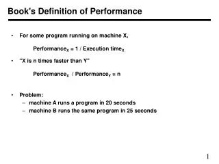
Book's Definition of Performance. For some program running on machine X, Performance X = 1 / Execution time X "X is n times faster than Y" Performance X / Performance Y = n Problem: machine A runs a program in 20 seconds machine B runs the same program in 25 seconds. Example.

E N D
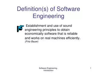
Book's Definition of Performance • For some program running on machine X, PerformanceX = 1 / Execution timeX • "X is n times faster than Y" PerformanceX / PerformanceY = n • Problem: • machine A runs a program in 20 seconds • machine B runs the same program in 25 seconds
Example • Our favorite program runs in 10 seconds on computer A, which has a 400 Mhz. clock. We are trying to help a computer designer build a new machine B, that will run this program in 6 seconds. The designer can use new (or perhaps more expensive) technology to substantially increase the clock rate, but has informed us that this increase will affect the rest of the CPU design, causing machine B to require 1.2 times as many clock cycles as machine A for the same program. What clock rate should we tell the designer to target?" • Don't Panic, can easily work this out from basic principles
Now that we understand cycles • A given program will require • some number of instructions (machine instructions) • some number of cycles • some number of seconds • We have a vocabulary that relates these quantities: • cycle time (seconds per cycle) • clock rate (cycles per second) • CPI (cycles per instruction) a floating point intensive application might have a higher CPI • MIPS (millions of instructions per second)this would be higher for a program using simple instructions
Performance • Performance is determined by execution time • Do any of the other variables equal performance? • # of cycles to execute program? • # of instructions in program? • # of cycles per second? • average # of cycles per instruction? • average # of instructions per second? • Common pitfall: thinking one of the variables is indicative of performance when it really isn’t.
CPI Example • Suppose we have two implementations of the same instruction set architecture (ISA). For some program,Machine A has a clock cycle time of 10 ns. and a CPI of 2.0 Machine B has a clock cycle time of 20 ns. and a CPI of 1.2 What machine is faster for this program, and by how much? • If two machines have the same ISA which of our quantities (e.g., clock rate, CPI, execution time, # of instructions, MIPS) will always be identical?
# of Instructions Example • A compiler designer is trying to decide between two code sequences for a particular machine. Based on the hardware implementation, there are three different classes of instructions: Class A, Class B, and Class C, and they require one, two, and three cycles (respectively). The first code sequence has 5 instructions: 2 of A, 1 of B, and 2 of CThe second sequence has 6 instructions: 4 of A, 1 of B, and 1 of C.Which sequence will be faster? How much?What is the CPI for each sequence?
MIPS example • Two different compilers are being tested for a 100 MHz. machine with three different classes of instructions: Class A, Class B, and Class C, which require one, two, and three cycles (respectively). Both compilers are used to produce code for a large piece of software.The first compiler's code uses 5 million Class A instructions, 1 million Class B instructions, and 1 million Class C instructions.The second compiler's code uses 10 million Class A instructions, 1 million Class B instructions, and 1 million Class C instructions. • Which sequence will be faster according to MIPS? • Which sequence will be faster according to execution time?
Benchmarks • Performance best determined by running a real application • Use programs typical of expected workload • Or, typical of expected class of applications e.g., compilers/editors, scientific applications, graphics, etc. • Small benchmarks • nice for architects and designers • easy to standardize • can be abused • SPEC (System Performance Evaluation Cooperative) • companies have agreed on a set of real program and inputs • can still be abused (Intel’s “other” bug) • valuable indicator of performance (and compiler technology)
SPEC ‘89 • Compiler “enhancements” and performance
SPEC ‘95 Does doubling the clock rate double the performance? Can a machine with a slower clock rate have better performance?
Amdahl's Law Execution Time After Improvement = Execution Time Unaffected +( Execution Time Affected / Amount of Improvement ) • Example: "Suppose a program runs in 100 seconds on a machine, with multiply responsible for 80 seconds of this time. How much do we have to improve the speed of multiplication if we want the program to run 4 times faster?" How about making it 5 times faster? • Principle: Make the common case fast
Example • Suppose we enhance a machine making all floating-point instructions run five times faster. If the execution time of some benchmark before the floating-point enhancement is 10 seconds, what will the speedup be if half of the 10 seconds is spent executing floating-point instructions? • We are looking for a benchmark to show off the new floating-point unit described above, and want the overall benchmark to show a speedup of 3. One benchmark we are considering runs for 100 seconds with the old floating-point hardware. How much of the execution time would floating-point instructions have to account for in this program in order to yield our desired speedup on this benchmark?
Remember • Performance is specific to a particular program/s • Total execution time is a consistent summary of performance • For a given architecture performance increases come from: • increases in clock rate (without adverse CPI affects) • improvements in processor organization that lower CPI • compiler enhancements that lower CPI and/or instruction count • Pitfall: expecting improvement in one aspect of a machine’s performance to affect the total performance • You should not always believe everything you read! Read carefully! (see newspaper articles, e.g., Exercise 2.37)
Where we are headed • Single Cycle Problems: • what if we had a more complicated instruction like floating point? • wasteful of area • One Solution: • use a “smaller” cycle time and use different numbers of cycles for each instruction using a “multicycle” datapath:
31 26 25 21 20 16 15 11 10 6 5 0 R-TYPE REG 1 REG 2 DST SHIFT AMOUNT ADD/AND/OR/SLT 31 26 25 21 20 16 15 11 10 6 5 0 31 26 25 21 20 16 15 11 10 6 5 0 31 26 25 21 20 16 15 11 10 6 5 0 BRANCH ADDRESS OFFSET LOAD ADDRESS OFFSET STORE ADDRESS OFFSET REG 1 REG 1 REG 1 REG 2 REG 2 REG 2 SW BEQ/BNE LW 31 26 25 21 20 16 15 11 10 6 5 0 JUMP JUMP ADDRESS MIPS Instruction Format Again
Operation for Each Instruction LW: 1. READ INST 2. READ REG 1 READ REG 2 3. ADD REG 1 + OFFSET 4. READ MEM 5. WRITE REG2 SW: 1. READ INST 2. READ REG 1 READ REG 2 3. ADD REG 1 + OFFSET 4. WRITE MEM 5. R-Type: 1. READ INST 2. READ REG 1 READ REG 2 3. OPERATE on REG 1 / REG 2 4. 5. WRITE DST BR-Type: 1. READ INST 2. READ REG 1 READ REG 2 3. SUB REG 2 from REG 1 4. 5. JMP-Type: 1. READ INST 2. 3. 4. 5.
Multicycle Approach • We will be reusing functional units • Break up the instruction execution in smaller steps • Each functional unit is used for a specific purpose in one cycle • Balance the work load • ALU used to compute address and to increment PC • Memory used for instruction and data • At the end of cycle, store results to be used again • Need additional registers • Our control signals will not be determined solely by instruction • e.g., what should the ALU do for a “subtract” instruction? • We’ll use a finite state machine for control
Review: finite state machines • Finite state machines: • a set of states and • next state function (determined by current state and the input) • output function (determined by current state and possibly input) • We’ll use a Moore machine (output based only on current state)
4 M U X 25-00 PC M U X 25-21 M U X M U X RA1 REG FILE A R RD1 I R 20-16 RA2 A L U ALU M U X B R M U X RD2 WA WD BR COND MEM MEM Add Add 15-11 BNE Data Out Data Out D R Sign Ext Shift Left 2 BEQ 15-00 ALU CON Data In Data In M U X JUMP 05-00 ALUOP CONTROL 31-26 Multi-Cycle DataPath Operation
Five Execution Steps • Instruction Fetch • Instruction Decode and Register Fetch • Execution, Memory Address Computation, or Branch Completion • Memory Access or R-type instruction completion • Write-back step INSTRUCTIONS TAKE FROM 3 - 5 CYCLES!
Step 1: Instruction Fetch • Use PC to get instruction and put it in the Instruction Register. • Increment the PC by 4 and put the result back in the PC. • Can be described succinctly using RTL "Register-Transfer Language" IR = Memory[PC]; PC = PC + 4;Can we figure out the values of the control signals?What is the advantage of updating the PC now?
Step 2: Instruction Decode and Register Fetch • Read registers rs and rt in case we need them • Compute the branch address in case the instruction is a branch • RTL: A = Reg[IR[25-21]]; B = Reg[IR[20-16]]; ALUOut = PC + (sign-extend(IR[15-0]) << 2); • We aren't setting any control lines based on the instruction type (we are busy "decoding" it in our control logic)
Step 3 (instruction dependent) • ALU is performing one of three functions, based on instruction type • Memory Reference: ALUOut = A + sign-extend(IR[15-0]); • R-type: ALUOut = A op B; • Branch: if (A==B) PC = ALUOut;
Step 4 (R-type or memory-access) • Loads and stores access memory MDR = Memory[ALUOut]; or Memory[ALUOut] = B; • R-type instructions finish Reg[IR[15-11]] = ALUOut;The write actually takes place at the end of the cycle on the edge
Write-back step • Reg[IR[20-16]]= MDR; What about all the other instructions?
31 26 25 21 20 16 15 11 10 6 5 0 R-TYPE REG 1 REG 2 DST SHIFT AMOUNT ADD/AND/OR/SLT 31 26 25 21 20 16 15 11 10 6 5 0 31 26 25 21 20 16 15 11 10 6 5 0 31 26 25 21 20 16 15 11 10 6 5 0 BRANCH ADDRESS OFFSET LOAD ADDRESS OFFSET STORE ADDRESS OFFSET REG 1 REG 1 REG 1 REG 2 REG 2 REG 2 SW BEQ/BNE LW 31 26 25 21 20 16 15 11 10 6 5 0 JUMP JUMP ADDRESS Instruction Format
Operation for Each Instruction LW: 1. READ INST 2. READ REG 1 READ REG 2 3. ADD REG 1 + OFFSET 4. READ MEM 5. WRITE REG2 SW: 1. READ INST 2. READ REG 1 READ REG 2 3. ADD REG 1 + OFFSET 4. WRITE MEM 5. R-Type: 1. READ INST 2. READ REG 1 READ REG 2 3. OPERATE on REG 1 / REG 2 4. 5. WRITE DST BR-Type: 1. READ INST 2. READ REG 1 READ REG 2 3. SUB REG 2 from REG 1 4. 5. JMP-Type: 1. READ INST 2. 3. 4. 5.
4 M U X 25-00 PC M U X 25-21 M U X M U X RA1 REG FILE A R RD1 I R 20-16 RA2 A L U ALU M U X B R M U X RD2 WA WD BR COND MEM MEM Add Add 15-11 BNE Data Out Data Out D R Sign Ext Shift Left 2 BEQ 15-00 ALU CON Data In Data In M U X JUMP 05-00 ALUOP CONTROL 31-26 Multi-Cycle DataPath Operation
25-00 PC M U X 25-21 M U X A R 20-16 RA1 REG FILE RD1 ALU RA2 B R M U X 4 M U X MEM Add RD2 WA 15-11 WD BR COND Data Out Sign Ext Shift Left 2 D R 15-00 ALU CON BNE Data In BEQ 05-00 M U X ALUOP JUMP 31-26 LW Operation on Multi-Cycle Data Path: C1 M U X I R A L U CONTROL
25-00 PC M U X 25-21 M U X A R 20-16 RA1 REG FILE RD1 ALU RA2 B R M U X 4 M U X MEM Add RD2 WA 15-11 WD BR COND Data Out Sign Ext Shift Left 2 D R 15-00 ALU CON BNE Data In BEQ 05-00 M U X ALUOP JUMP 31-26 LW Operation on Multi-Cycle Data Path: C2 M U X I R A L U CONTROL
25-00 PC M U X 25-21 M U X A R 20-16 RA1 REG FILE RD1 ALU RA2 B R M U X 4 M U X MEM Add RD2 WA 15-11 WD BR COND Data Out Sign Ext Shift Left 2 D R 15-00 ALU CON BNE Data In BEQ 05-00 M U X ALUOP JUMP 31-26 LW Operation on Multi-Cycle Data Path: C3 M U X I R A L U CONTROL
25-00 PC M U X 25-21 M U X A R 20-16 RA1 REG FILE RD1 ALU RA2 B R M U X 4 M U X MEM Add RD2 WA 15-11 WD BR COND Data Out Sign Ext Shift Left 2 D R 15-00 ALU CON BNE Data In BEQ 05-00 M U X ALUOP JUMP 31-26 LW Operation on Multi-Cycle Data Path: C4 M U X I R A L U CONTROL
25-00 PC M U X 25-21 M U X A R 20-16 RA1 REG FILE RD1 ALU RA2 B R M U X 4 M U X MEM Add RD2 WA 15-11 WD BR COND Data Out Sign Ext Shift Left 2 D R 15-00 ALU CON BNE Data In BEQ 05-00 M U X ALUOP JUMP 31-26 LW Operation on Multi-Cycle Data Path: C5 M U X I R A L U CONTROL
25-00 PC M U X 25-21 M U X 20-16 RA1 REG FILE RD1 ALU RA2 M U X 4 M U X MEM Add RD2 WA 15-11 WD BR COND Data Out Sign Ext Shift Left 2 D R 15-00 ALU CON BNE Data In BEQ 05-00 M U X ALUOP JUMP 31-26 SW Operation on Multi-Cycle Data Path: C1 M U X A R I R A L U B R CONTROL
25-00 PC M U X 25-21 M U X A R 20-16 RA1 REG FILE RD1 ALU RA2 B R M U X 4 M U X MEM Add RD2 WA 15-11 WD BR COND Data Out Sign Ext Shift Left 2 D R 15-00 ALU CON BNE Data In BEQ 05-00 M U X ALUOP JUMP 31-26 SW Operation on Multi-Cycle Data Path: C2 M U X I R A L U CONTROL
25-00 PC M U X 25-21 M U X A R 20-16 RA1 REG FILE RD1 ALU RA2 B R M U X 4 M U X MEM Add RD2 WA 15-11 WD BR COND Data Out Sign Ext Shift Left 2 D R 15-00 ALU CON BNE Data In BEQ 05-00 M U X ALUOP JUMP 31-26 SW Operation on Multi-Cycle Data Path: C3 M U X I R A L U CONTROL
25-00 PC M U X 25-21 M U X A R 20-16 RA1 REG FILE RD1 ALU RA2 B R M U X 4 M U X MEM Add RD2 WA 15-11 WD BR COND Data Out Sign Ext Shift Left 2 D R 15-00 ALU CON BNE Data In BEQ 05-00 M U X ALUOP JUMP 31-26 SW Operation on Multi-Cycle Data Path: C4 M U X I R A L U CONTROL
25-00 PC M U X 25-21 M U X 20-16 RA1 REG FILE RD1 ALU RA2 M U X 4 M U X MEM Add RD2 WA 15-11 WD BR COND Data Out Sign Ext Shift Left 2 D R 15-00 ALU CON BNE Data In BEQ 05-00 M U X ALUOP JUMP 31-26 R-TYPE Operation on Multi-Cycle Data Path: C1 M U X A R I R A L U B R CONTROL
25-00 PC M U X 25-21 M U X A R 20-16 RA1 REG FILE RD1 ALU RA2 B R M U X 4 M U X MEM Add RD2 WA 15-11 WD BR COND Data Out Sign Ext Shift Left 2 D R 15-00 ALU CON BNE Data In BEQ 05-00 M U X ALUOP JUMP 31-26 R-TYPE Operation on Multi-Cycle Data Path: C2 M U X I R A L U CONTROL
25-00 PC M U X 25-21 M U X A R 20-16 RA1 REG FILE RD1 ALU RA2 B R M U X 4 M U X MEM Add RD2 WA 15-11 WD BR COND Data Out Sign Ext Shift Left 2 D R 15-00 ALU CON BNE Data In BEQ 05-00 M U X ALUOP JUMP 31-26 R-TYPE Operation on Multi-Cycle Data Path: C3 M U X I R A L U CONTROL
25-00 PC M U X 25-21 M U X A R 20-16 RA1 REG FILE RD1 ALU RA2 B R M U X 4 M U X MEM Add RD2 WA 15-11 WD BR COND Data Out Sign Ext Shift Left 2 D R 15-00 ALU CON BNE Data In BEQ 05-00 M U X ALUOP JUMP 31-26 R-TYPE Operation on Multi-Cycle Data Path: C4 M U X I R A L U CONTROL
25-00 PC M U X 25-21 M U X 20-16 RA1 REG FILE RD1 ALU RA2 M U X 4 M U X MEM Add RD2 WA 15-11 WD BR COND Data Out Sign Ext Shift Left 2 D R 15-00 ALU CON BNE Data In BEQ 05-00 M U X ALUOP JUMP 31-26 BR Operation on Multi-Cycle Data Path: C1 M U X A R I R A L U B R CONTROL
25-00 PC M U X 25-21 M U X A R 20-16 RA1 REG FILE RD1 ALU RA2 B R M U X 4 M U X MEM Add RD2 WA 15-11 WD BR COND Data Out Sign Ext Shift Left 2 D R 15-00 ALU CON BNE Data In BEQ 05-00 M U X ALUOP JUMP 31-26 BR Operation on Multi-Cycle Data Path: C2 M U X I R A L U CONTROL
25-00 PC M U X 25-21 M U X A R 20-16 RA1 REG FILE RD1 ALU RA2 B R M U X 4 M U X MEM Add RD2 WA 15-11 WD BR COND Data Out Sign Ext Shift Left 2 D R 15-00 ALU CON BNE Data In BEQ 05-00 M U X ALUOP JUMP 31-26 BR Operation on Multi-Cycle Data Path: C3 M U X I R A L U CONTROL
25-00 PC M U X 25-21 M U X 20-16 RA1 REG FILE RD1 ALU RA2 M U X 4 M U X MEM Add RD2 WA 15-11 WD BR COND Data Out Sign Ext Shift Left 2 D R 15-00 ALU CON BNE Data In BEQ 05-00 M U X ALUOP JUMP 31-26 JUMP Operation on Multi-Cycle Data Path: C1 M U X A R I R A L U B R CONTROL
25-00 PC M U X 25-21 M U X A R 20-16 RA1 REG FILE RD1 ALU RA2 B R M U X 4 M U X MEM Add RD2 WA 15-11 WD BR COND Data Out Sign Ext Shift Left 2 D R 15-00 ALU CON BNE Data In BEQ 05-00 M U X ALUOP JUMP 31-26 JUMP Operation on Multi-Cycle Data Path: C2 M U X I R A L U CONTROL
Simple Questions • How many cycles will it take to execute this code? lw $t2, 0($t3) lw $t3, 4($t3) beq $t2, $t3, Label #assume not add $t5, $t2, $t3 sw $t5, 8($t3)Label: ... • What is going on during the 8th cycle of execution? • In what cycle does the actual addition of $t2 and $t3 takes place?
Implementing the Control • Value of control signals is dependent upon: • what instruction is being executed • which step is being performed • Use the information we’ve accumulated to specify a finite state machine • specify the finite state machine graphically, or • use micro-programming • Implementation can be derived from specification